


2010 fans and spal


Senior Member
Joined: Jul 2007
Posts: 2,036
Likes: 2
From: Maine
What Controller are you using ?? My setup is this: The AC wire is tied into the AC clutch wire in the loom that runs along the valve cover (Batt side). I get my ignition input from one of the wires from the plug that the original fan plugged into, all taped and in a loom. The fans are connected together with 10ga wire split for the pos and neg sides and are on the controller as such (two fan grounds on ground) (two fan pos wires on the output connection. Although I have the under-drive pulley jumper, I do not use it. (FK50P controller) For the life of me I cannot understand the need for that resistor in that system, that is only needed for long battery runs (voltage drop). Also, remember these controllers come from Brian set for 180deg thermostats, they have to be adjusted up for our trucks 192-195 thermostats. If only one fan is running in a parallel setup...something is wrong. On a side note, I would put at least one bracket on the bottom...prevents vibration of the shroud.

Senior Member
Joined: Apr 2010
Posts: 646
Likes: 0
From: Las Vegas
Not sure what's going on with the fan, tried all temps with the dc fk50p
Will double check the wiring again when I get a chance, there's a possibility the controller sees the fan as low impedance/short, but the filter runs both fans correctly
Which wires did you tap into for the ac and ignition sources, specifically color or a picture
The underdrive is needed for those with overheating issues at idle with underdrive pulleys
Will double check the wiring again when I get a chance, there's a possibility the controller sees the fan as low impedance/short, but the filter runs both fans correctly
Which wires did you tap into for the ac and ignition sources, specifically color or a picture
The underdrive is needed for those with overheating issues at idle with underdrive pulleys
Last edited by BLFX4K; Oct 11, 2010 at 02:09 AM.
Senior Member
Joined: Jul 2007
Posts: 2,036
Likes: 2
From: Maine
Not sure what's going on with the fan, tried all temps with the dc fk50p
Will double check the wiring again when I get a chance, there's a possibility the controller sees the fan as low impedance/short, but the filter runs both fans correctly
Which wires did you tap into for the ac and ignition sources, specifically color or a picture
The underdrive is to ensure the water pump isn't slowed down too much and to run the fans appropriately
Will double check the wiring again when I get a chance, there's a possibility the controller sees the fan as low impedance/short, but the filter runs both fans correctly
Which wires did you tap into for the ac and ignition sources, specifically color or a picture
The underdrive is to ensure the water pump isn't slowed down too much and to run the fans appropriately

Senior Member
Joined: Feb 2004
Posts: 10,390
Likes: 10
I would suggest getting rid of that filter, it isn't designed to do what it's doing, something else is wrong with the wiring or something. Try to take a pic of your controller wiring set-up. Same as with DM, can't get a pic of the actual tap as I have it all in a harness. Try to get a wiring schematic for the truck and follow the color coded wires in the harness, open the harness and tap into it (AC). Use a test light to find the ignition wire in the plug (engine side) of the OEM fan, that is what I used for the ign tap. Wire up the controller as per the instructions. Confused with the statement "tried all temps" on the controller. The temp is controlled by that tiny screw on that blue square thing...you adjust the temp so the fans will start when the thermostat opens (usually 192 deg) should be done with a temp probe (or Gryphon/Edge) that shows actual coolant temp. Your wrong with your thoughts about the under-drive pulley jumper. As per the instructions you 'may' put a jumper on the pins if you are running under drive pulleys and experience overheating..it will make the fans run at 10% even when cold. Unless you have a bum fan, I don't know what else to say..just go by the instructions and you should be set...Totally forget about the under drive pulley jumper for now until you get things up and running......without that resistor!

As for the noise - it's a function of the slew rate (a.k.a rise/fall times) of the PWM waveform leading and trailing edges. This induces audible harmonics in the motor assembly. Designers can tailor same to accomodate specific fans, but the fan type needs to exist first

MGD
Senior Member
Joined: Apr 2010
Posts: 646
Likes: 0
From: Las Vegas
Are you running one wire per negative/positive outlet spade terminal to the controller or running wiring off of the original wires to the second fan? POS, NEG to fan 1 and tapping into these wires for the second fan, couldn't get both to run this way and same with the second setup, one wire per negative and positive terminal, it shorts out whenever i plug the positive on the second fan in
I know how the temps work, just having issues with only one of the fans working correctly, they both work, but i may have to wire it a little differently on the second fan?
I know how the temps work, just having issues with only one of the fans working correctly, they both work, but i may have to wire it a little differently on the second fan?
Last edited by BLFX4K; Oct 11, 2010 at 06:20 PM.

Senior Member
Joined: May 2009
Posts: 102
Likes: 0
From: Quad Cities, IL
Are you running one wire per negative/positive outlet spade terminal to the controller or running wiring off of the original wires to the second fan?
I know how the temps work, just having issues with only one of the fans working correctly, they both work, but i may have to wire it a little differently on the second fan?
I know how the temps work, just having issues with only one of the fans working correctly, they both work, but i may have to wire it a little differently on the second fan?
On another note, ordered my fans and 2 of the Ford wiring harnesses today from carpartsestore, already got my FK85 controller from DC. Can't wait to get this done.
Senior Member
Joined: Feb 2004
Posts: 10,390
Likes: 10
You're running the fans in parallel, not series, right (the negative from both fans goes to the negative output on the controller, the positive from both fans goes to the positive output on the controller)? Pretty sure you could really mess the controller up if you tried to run these things in series (negative from one fan to positive of the other, then the remaining two leads to the controller).
On another note, ordered my fans and 2 of the Ford wiring harnesses today from carpartsestore, already got my FK85 controller from DC. Can't wait to get this done.
On another note, ordered my fans and 2 of the Ford wiring harnesses today from carpartsestore, already got my FK85 controller from DC. Can't wait to get this done.
Actually easier on the controller this way
I think, from the prose it's wired in parallel ... somethin; wierd goin' on here. Perhaps try one fan only. Confirm. Disconnect first fan, connect second. Confirm. Both should operate Ed Zachary the same. Then connect both again. (inline ammeter would help here.)
MGD
Senior Member
Joined: Apr 2010
Posts: 646
Likes: 0
From: Las Vegas
Yes, it's wired in parallel, negative from both fans to negative on controller. Positive on both fans to positive on controller.
Both fans run if the positive from the second fan (passenger side) is on the input from the battery, found this out by accident when the wire touched, both fans run about 50% when that happens but there's no way to shut it off besides drain the battery, so both fans are working.
Im going to swap the wires around from the fan thats working to that fan that isn't running, see if it changes things up, but from what Brian at DC knows, it needs the filter. I've given him a lot of information regarding the fans and the wiring setup i have, it's all correct but something funny indeed is happening!
Both fans run if the positive from the second fan (passenger side) is on the input from the battery, found this out by accident when the wire touched, both fans run about 50% when that happens but there's no way to shut it off besides drain the battery, so both fans are working.
Im going to swap the wires around from the fan thats working to that fan that isn't running, see if it changes things up, but from what Brian at DC knows, it needs the filter. I've given him a lot of information regarding the fans and the wiring setup i have, it's all correct but something funny indeed is happening!
Senior Member
Joined: Jul 2007
Posts: 2,036
Likes: 2
From: Maine
I hope you meant to say 'output' side of the controller with the Pos. wires from the fans. Also, have you got the 'ign.' wire connected yet? That ign wire on the controller is what triggers the controller on or off, if I remember correctly. If that is not connected the fans will run until the rad temp comes down with the engine off. It's highly un-likely, but you could have a bad controller. I would like to see a sketch of your wiring set-up.
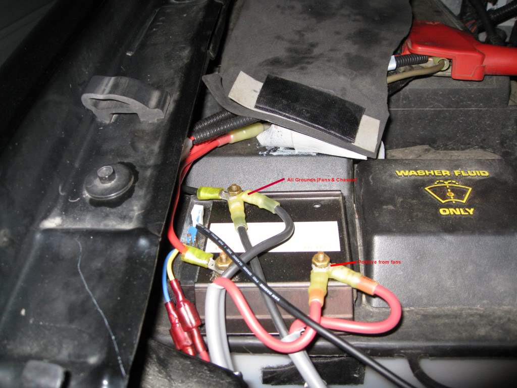
Senior Member
Joined: Apr 2010
Posts: 646
Likes: 0
From: Las Vegas
Yes, output for the positive. Ignition wire is connected and does in fact trigger the fans on and off.
Ill try and show you what it looks like when I get a chance, would hope not to have a bad controller, i guess we'll see, waiting a month for these things is bad enough as it is
Ill try and show you what it looks like when I get a chance, would hope not to have a bad controller, i guess we'll see, waiting a month for these things is bad enough as it is
Senior Member
Joined: Apr 2010
Posts: 646
Likes: 0
From: Las Vegas
Sam1947: mine is wired exactly like your setup
yet only one fan works, the positive for the second fan is what's shorting them and shutting them off, either fan works depending on which one i connect to both Ground and positive. If i connect both of them it will run until the positive to the second fan is connected and shuts everything off.
The jumper works for the a/c, both a/c and ignition wires are tapped and function correctly
yet only one fan works, the positive for the second fan is what's shorting them and shutting them off, either fan works depending on which one i connect to both Ground and positive. If i connect both of them it will run until the positive to the second fan is connected and shuts everything off.
The jumper works for the a/c, both a/c and ignition wires are tapped and function correctly
Senior Member
Joined: Feb 2004
Posts: 10,390
Likes: 10
Sam1947: mine is wired exactly like your setup
yet only one fan works, the positive for the second fan is what's shorting them and shutting them off, either fan works depending on which one i connect to both Ground and positive. If i connect both of them it will run until the positive to the second fan is connected and shuts everything off.
The jumper works for the a/c, both a/c and ignition wires are tapped and function correctly
yet only one fan works, the positive for the second fan is what's shorting them and shutting them off, either fan works depending on which one i connect to both Ground and positive. If i connect both of them it will run until the positive to the second fan is connected and shuts everything off.
The jumper works for the a/c, both a/c and ignition wires are tapped and function correctly
MGD