
2 switches, 1 light question


2 switches, 1 light question
Is it possible to wire 2 switches to 1 light?
I have flush mounted cubes mounted in my rear bumper, They are wired directly to my reverse light harness. Is it possible for me to wire a second switch to these lights that I can turn off and on as I needed?
I tried to look online for a diagram to do this but had no luck, was hoping i could find help here.
Thanks in advance

Technical Article Contributor
Joined: Mar 2005
Posts: 4,387
Likes: 9
From: OH-IO
You could just use a 5 pin relay. By wiring the relay up to control the lights, you could splice your reverse lights into the normally closed contact on the relay, so when the switch is off the lights will come on with your reverse lights. When you switch them on manually the relay will close the normally open contact, powering on the lights. At the same time, the normally closed contact will open, preventing back feed into your reverse lights, eliminating the need for a diode.
Last edited by 05RedFX4; May 4, 2016 at 12:25 AM.
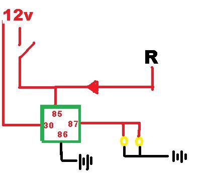
A) "30" is connected directly to the battery
B) "85" is connected to a "Switch harness" and the power from the reverse lights
C) "86" is grounded
D) "87" is to the lights, which are grounded
05RedFX4
do you have a drawing of your concept?
Global Moderator &
Senior Member
Senior Member

Joined: Aug 2005
Posts: 21,337
Likes: 159
From: DFW
Or flip it and you load runs through your switch, which defeats the benifit of the relay
30 output to lights
86 ground
85 Reverse
87 12v ignition
87A switch 12v
30 output to lights
86 ground
85 Reverse
87 12v ignition
87A switch 12v
Trending Topics
Global Moderator &
Senior Member
Senior Member
Joined: Aug 2005
Posts: 21,337
Likes: 159
From: DFW
This is assuming you use appropriate fuses on the 12v power source, as well as probably a good idea on your R trigger
So just to make sure I get it right Patman
A) "30" is connected directly to the battery
B) "85" is connected to a "Switch harness" and the power from the reverse lights
C) "86" is grounded
D) "87" is to the lights, which are grounded
05RedFX4
do you have a drawing of your concept?
A) "30" is connected directly to the battery
B) "85" is connected to a "Switch harness" and the power from the reverse lights
C) "86" is grounded
D) "87" is to the lights, which are grounded
05RedFX4
do you have a drawing of your concept?
My numbers are ISO Standard relay callouts
30 should be ignition 12v (fused)
85 switched ignition 12v AND Reverse trigger with inline diode
86 ground
87 to lights
Technical Article Contributor
Joined: Mar 2005
Posts: 4,387
Likes: 9
From: OH-IO

Basically you would wire it up as follows,
pin 30 to your cube lights
pin 87a to your reverse light trigger
pin 87 to switched/fused 12v feed
pin 86 to secondary switch
pin 85 to ground
by wiring as above your cube lights will come on with your reverse lights like they do now, and when you flip the switch you can power them on manually and not back feed your reverse lights.
Last edited by 05RedFX4; May 4, 2016 at 10:41 AM.
Okay awesome, can I just buy any "Inline Diode" or is there a specific one I need?
Basically you would wire it up as follows,
pin 30 to your cube lights
pin 87a to your reverse light trigger
pin 87 to switched/fused 12v feed
pin 86 to secondary switch
pin 85 to ground
by wiring as above your cube lights will come on with your reverse lights like they do now, and when you flip the switch you can power them on manually and not back feed your reverse lights.
Awesome! Thank you sir!
Technical Article Contributor
Joined: Mar 2005
Posts: 4,387
Likes: 9
From: OH-IO
pins 30, 87, 87a are not polarity specific. You can send 12v dc thru them in either direction. They were designed to have pin 30 as input and 87, 87a as selectable outputs. But you can use it as a dual selectable input with a single output by using 87, 87a as inputs and 30 as output.
Now pins 85, 86 are polarity specific. If you feed dc current into the coil the wrong way, it will not move the contacts and nothing happens. so make sure you get the polarity correct on 85 and 86.
Now pins 85, 86 are polarity specific. If you feed dc current into the coil the wrong way, it will not move the contacts and nothing happens. so make sure you get the polarity correct on 85 and 86.
Last edited by 05RedFX4; May 4, 2016 at 10:57 AM.
Global Moderator &
Senior Member
Senior Member
Joined: Aug 2005
Posts: 21,337
Likes: 159
From: DFW
85 and 86 are interchangeable as long as one receives a power and one receives a ground
Your 30-87-87A complete the circuit to eachother, but you can send power through, or make a ground available through the relay if you wanted you control on the ground side
Your 30-87-87A complete the circuit to eachother, but you can send power through, or make a ground available through the relay if you wanted you control on the ground side