
Using TCS and parking aid switches for Aux lights


Thread Starter
|
Member
Joined: May 2009
Posts: 83
Likes: 0
From: Niceville, FL
Using TCS and parking aid switches for Aux lights
I bought a trim piece that has TCS and Parking Aid switches and I wanted to use them for aux lighting. My truck(05 FX4) has neither.
I found some schematics on SScully's album(thanks for posting those). The schematics are for an 07. This is what I think I know.
Parking Aid Pins and wires that I shoud tap into. Can I even use this switch? It seems like its a ground switch.
1 Ground to black
2 Labeled as on/off to DG-VT- Can I use this to my relay? 12v+ out?
6 Staus LED should go to VT-OG, Can I use it for 12v+ in?
4 Ground
8 Cluster and panel Illum to LB-RD Just double checking-Light brown wire with a red stripe
TCS has 6 pins and I could only find what 2 are for.
7 Ground
8 Cluster and Panel Illum to LB-RD
Can I find a plug to make things easier? If I can't find a plug, What is the best way to attach wires to the pins? Trim the plastic back and solder wire to each pin?
Thanks for any input.
Last edited by Merty; May 22, 2010 at 02:10 PM. Reason: spelling

Technical Article Contributor
Joined: Jun 2002
Posts: 10,511
Likes: 10
From: Under the flightpath of old ORD 22R
Does not make a difference, but the diagram for the PAM is from the 2006 EVTM, not the 2007 ( 2006 EVTM 131 1 Park Aid )

In this setup, you would run fused ( 1A ) power to the relay coil pin # 85, and use the PAM switch to switch ground to pin #86.
- Does the PAM switch click into place, or is this a momentary switch like the heated seat switch ?
The status LED is power from something, so you could use the power from the output of the relay normally open contacts ( pin #87 ) to drive this. Ground is as shown above for pins #1 & #4.
Pin #8 ( which is shown as light blue w/ red stripe ) would go to the instrumentation illumination ( output of the dimer switch ).
You might try a bone yard for the switch connector, else you will need to solder the wire directly to the switch. If you do this, you will need to try to get a heat sink on there, as you do not want to heat up the components in the switch ( they might stop working ).
Had to get the TCS diagram for the remainder
2006 EVTM cell on TCS

Same question on the switch, is this a momentary or std switch ?
The switch has the power in on pin #1, SPST switch out on pin # 2. Backlight illumination power on pin #8, ground on pin #7. The "on" illumination is pin #6 pwr and ground on pin #4. So tie the output of the relay this controls ( pin #87 ) to pin #6, and ground pin #4. The TCS ground that side of the indicator LED once the TCS is engaged ( that is why it is hot in run position on the top ).
In this setup, you would run fused ( 1A ) power to the relay coil pin # 85, and use the PAM switch to switch ground to pin #86.
- Does the PAM switch click into place, or is this a momentary switch like the heated seat switch ?
The status LED is power from something, so you could use the power from the output of the relay normally open contacts ( pin #87 ) to drive this. Ground is as shown above for pins #1 & #4.
Pin #8 ( which is shown as light blue w/ red stripe ) would go to the instrumentation illumination ( output of the dimer switch ).
You might try a bone yard for the switch connector, else you will need to solder the wire directly to the switch. If you do this, you will need to try to get a heat sink on there, as you do not want to heat up the components in the switch ( they might stop working ).
Had to get the TCS diagram for the remainder
2006 EVTM cell on TCS
Same question on the switch, is this a momentary or std switch ?
The switch has the power in on pin #1, SPST switch out on pin # 2. Backlight illumination power on pin #8, ground on pin #7. The "on" illumination is pin #6 pwr and ground on pin #4. So tie the output of the relay this controls ( pin #87 ) to pin #6, and ground pin #4. The TCS ground that side of the indicator LED once the TCS is engaged ( that is why it is hot in run position on the top ).
Last edited by SSCULLY; May 23, 2010 at 10:27 AM. Reason: Add in TCS info
Thread Starter
|
Member
Joined: May 2009
Posts: 83
Likes: 0
From: Niceville, FL
Thanks SSCULLY! I'm in the process of digesting this. To answer your question, I am 99% sure these are just std switches. I believe the Status LED is for the switches themselves, it looks like they illuminate "OFF".
Now the questions, For the PAM switch you mention pins 85, 86 and 87-those are pin locations on the fuse box. Which PAM pin(12v+ out) do I send to my driving light relay?
I'm sure the answer is in there, I am just having problems extracting it.
I can see all the pin numbers on the TCS switch, but the pam switch I can't see any. Would they happen to be arranged in a specific order? Hope I can find plugs, those pins are tiny.
I have a side question for you, -Adding defrost option, Is it worth buying a new fuse box with the option or add a circuit to the fuse box I have.
Thanks again for your help.
Thread Starter
|
Member
Joined: May 2009
Posts: 83
Likes: 0
From: Niceville, FL
Just took an Ohm meter to the PAM switch between pins 1 and 2. It only reads no resistance when the switch is pushed in so it must be an momentary switch. So much for my 99%. I'm tinkering with the other switch now.
DOH-Make that both are momentary on. -Can that be remedied with differant type of relay? A switching relay or something? Maybe I should just put those radio shack switches in and make it easy on myself.
DOH-Make that both are momentary on. -Can that be remedied with differant type of relay? A switching relay or something? Maybe I should just put those radio shack switches in and make it easy on myself.
Last edited by Merty; May 23, 2010 at 02:26 PM. Reason: Those dang switches update
Thread Starter
|
Member
Joined: May 2009
Posts: 83
Likes: 0
From: Niceville, FL
Double DOH and Eureka!
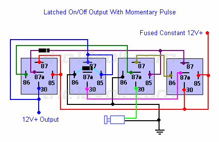
- So I was going crazy looking for pins 85,86,and 87 in all the Ford schemtics. Then I decided to look for what I remembered as "switching relay", surpisingly stumbled across a latching relay with pin numbers 85,86 and 87. I missed mention of that in your post. Needless to say a big light bulb appeared over my head.
- So I was going crazy looking for pins 85,86,and 87 in all the Ford schemtics. Then I decided to look for what I remembered as "switching relay", surpisingly stumbled across a latching relay with pin numbers 85,86 and 87. I missed mention of that in your post. Needless to say a big light bulb appeared over my head.
Technical Article Contributor
Joined: Jun 2002
Posts: 10,511
Likes: 10
From: Under the flightpath of old ORD 22R
You can spend the money on a latching relay ( ELK Security products has something that would do the trick, but they are ~ 30.00 each ) or just google latch relay diagram, and make a latching relay circuit out of standard Bosch automotive relays.
Thing is either it is a single relay, and power needs to be shut off ( i.e. turn off the truck ) to make the circuit drop

Or you need 3 relays, and need to make a momentary on ( i.e. TCS and PAM switch ) and anther switch to turn it off.
At this point might just want to get some round Radio Shack switches, and put them in the panel next to the cigar lighter.
Thing is either it is a single relay, and power needs to be shut off ( i.e. turn off the truck ) to make the circuit drop
Or you need 3 relays, and need to make a momentary on ( i.e. TCS and PAM switch ) and anther switch to turn it off.
At this point might just want to get some round Radio Shack switches, and put them in the panel next to the cigar lighter.
Thread Starter
|
Member
Joined: May 2009
Posts: 83
Likes: 0
From: Niceville, FL
Thanks again. Been reading up on Latching relays off and on all afternoon and saw those schematics. Dont want to beat a dead horse to much but a SPDT(single pole dual throw-right?) latching relay wont do the trick?
These switches are the third idea. First plan was to use a headlight w/fogs switch, so I could turn one set or other or all. Then I bought some radio shack switches and planned on mounting them them next to cig lighter. I saw this trim piece on ebay and it had those switches and defrost and figured what the heck-How hard could it be?
I'll googled the ELK security products, Would you happen to know the part number? I really appreciate the input.
Trending Topics
Technical Article Contributor
Joined: Jun 2002
Posts: 10,511
Likes: 10
From: Under the flightpath of old ORD 22R
For this setup ( if you can find one ) a SPST Latching relay would work just fine.
The cost of this is what I mentioned ( 2 x ~ 30.00 @ | usually DPDT atching relays ). Usually these relays are different bases, so female terminal ends won't do the trick, so you would also need 2 bases. Just another 70.00 + to make these switches work. Dayton is another mfgr of DPDT relays.
The cost of this is what I mentioned ( 2 x ~ 30.00 @ | usually DPDT atching relays ). Usually these relays are different bases, so female terminal ends won't do the trick, so you would also need 2 bases. Just another 70.00 + to make these switches work. Dayton is another mfgr of DPDT relays.

