
Wiring Diagram Help (Driving Lights)


Thread Starter
|
Member
Joined: Aug 2006
Posts: 42
Likes: 0
From: NC
Wiring Diagram Help (Driving Lights)
I mounted a pair of driving lights behind my grille yesterday, and am still working on figuring out the wiring. I want the lights to be wired to come on with the high beams, but I also want the option of a switch so the lights can be run on their own. I've read through a lot of threads today to piece this together. Here's what I came up with:

Does this look pretty close? What should go to the third connection on the switch... and one thread mentioned a second relay? Please excuse the crude diagram, but I'm just trying to learn this electrical stuff. Thanks in advance for any advice - I really don't want to burn my truck down!
Rob
Does this look pretty close? What should go to the third connection on the switch... and one thread mentioned a second relay? Please excuse the crude diagram, but I'm just trying to learn this electrical stuff. Thanks in advance for any advice - I really don't want to burn my truck down!
Rob

Senior Member
Joined: Jul 2004
Posts: 6,200
Likes: 39
From: Easton, Pa.
The only difference from your posted circuit is to drive the relay from the hi-beam lead up front thru a diode, not off the switch because everything is relayed from the factory and adding a blocking diode..
Then to power the AUX lights from a switch direct that operates the relay again without back feeding to the hi beams again. The diode blocks this from happening.
There are other ways to do it but this is the least wiring.
I have aux yellow fogs on a relay and switch between the driving and fogs when needed.
All that is done is swap power between the light sets with a relay that has double pole double throw contacts, power the relay with 12 volts and use a single wire thru the firewall to switch ground on and off.
Your not supposed to run aux lights with high beams but that's your decision.
This is why driving lights are turned off when going to highs.
Good luck with it.

Technical Article Contributor
Joined: Jun 2002
Posts: 10,511
Likes: 10
From: Under the flightpath of old ORD 22R
Rob,
Seems pretty accurate to me. If you want a suggestion for the "pinkish" color lead on the SPDT switch to the question mark. Maybe the brown wire on the headlamp switch ? This is the parking lamps, and might be a good option, if you want to have at least the parking lamps on when the aux lamps are on, and so if you open the door with at least the parking lamps on, you will get the dinger to remind you. That might service the function of the hot in run position, of not leaving them on ??
Using :
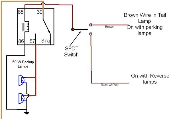
You can see the pin assignments if you do not have them already. The ground can be a common point, or 2 separate points, as long as you are sure both points are frame ground to the battery.
The one lead I call out in the diagram is for the reverse circuit, don't go looking for that black w/ pink stripe wire. Function wise, this would work. As reverse lights, this diagram is basically what I have installed, and it works fine.
The correct one from the MFS would be gray w/ orange stripe wire.
https://www.f150online.com/galleries...028-167986.jpg
Seems pretty accurate to me. If you want a suggestion for the "pinkish" color lead on the SPDT switch to the question mark. Maybe the brown wire on the headlamp switch ? This is the parking lamps, and might be a good option, if you want to have at least the parking lamps on when the aux lamps are on, and so if you open the door with at least the parking lamps on, you will get the dinger to remind you. That might service the function of the hot in run position, of not leaving them on ??
Using :
You can see the pin assignments if you do not have them already. The ground can be a common point, or 2 separate points, as long as you are sure both points are frame ground to the battery.
The one lead I call out in the diagram is for the reverse circuit, don't go looking for that black w/ pink stripe wire. Function wise, this would work. As reverse lights, this diagram is basically what I have installed, and it works fine.
The correct one from the MFS would be gray w/ orange stripe wire.
https://www.f150online.com/galleries...028-167986.jpg
Thread Starter
|
Member
Joined: Aug 2006
Posts: 42
Likes: 0
From: NC
Thanks for the help!
Bluegrass, so are you saying to run the YELLOW high beam lead through a diode, straight to the relay in my diagram?
Then how does that reconfigure my switch connections? And I'd need a different type of switch, right?
Also, I was under the impression that to be street legal, Driving Lights had to be run with high beams, and Fogs/highbeams should not be on at the same time. Is that wrong? I do want to keep it at least close to legal...
Thread Starter
|
Member
Joined: Aug 2006
Posts: 42
Likes: 0
From: NC
SSCULLY,
I had actually gotten this idea of using a center off switch from one of your posts in another thread, so I'm definitely glad for your help.
I'm not sure I completely understand what the 'pinkish' wire from the switch is for. Is it to supply an alternate power source for the lights (besides the highbeams)? So if I were to use the BROWN parking lamps wire, then I would need to run the parking lamps in order to supply power to that ON side of the switch? It would be cool to have that reminder, so they couldn't get left on by mistake. But that 'pink' wire can go to anything that is on when the ignition is on, right?
Thanks again for the help!
Technical Article Contributor
Joined: Jun 2002
Posts: 10,511
Likes: 10
From: Under the flightpath of old ORD 22R
Originally Posted by danger k
..<snip>...I'm not sure I completely understand what the 'pinkish' wire from the switch is for. Is it to supply an alternate power source for the lights (besides the highbeams)? So if I were to use the BROWN parking lamps wire, then I would need to run the parking lamps in order to supply power to that ON side of the switch? It would be cool to have that reminder, so they couldn't get left on by mistake. But that 'pink' wire can go to anything that is on when the ignition is on, right?..<snip>...
The dinger, is the typical headlamp dinger, that is active any time the parking or headlamps are on, and the door opens, with the key off.
This can also be any hot in run position circuit in the truck.
The other side of the switch, for the on with high beams is the MFS circuit that is gray w/ orange stripe wire.
As for DOT laws, state to state are different, but I think IL is :
Fog lamps can be on, as long as they are not obstructing the vision of on coming motorists.
Driving lamps must be turned off with on coming traffic ( driving lamps, not fog lamps ).
Neither can be on with high beams.
No more then 3 AUX lamps can be lit at one time ( 1 pair + 1 single lamp )
Got me why IL added the not on with high beams, approaching motorist means the headlamps are to be in the low or dipped position, which would turn off the driving lamps in this case. ??
Your state can vary quite a bit, so check state and local city ordnances to confirm what is the law in your state, and if LEOs actually care about this.
I would take a SWAG ( not fact ) that LEO won't care about any of the above if they are aimed correctly. On ST.net, quite a few break the aux lamp height law by mounting driving lamps either under or over the mirrors on motorcycles. Not a single one had been clipped for them by a LEO. This is the law about Aux lamps not being higher then headlamps ( to stop aux lamps on roll bars, from being illuminated while on the road )
Thread Starter
|
Member
Joined: Aug 2006
Posts: 42
Likes: 0
From: NC
Thanks again, SSCULLY - I think that clears it up. I probably will go with the parking lamp wire, I really like the idea of the alert when leaving the truck.
One more thing I'm still not sure of (I'm still trying to search for it), but how do I access those wires (high beam/parking)? When you mention the headlamp switch, do you mean the connections behind the actual **** in the dash? What do you use to splice into them?
Thanks for the great info - I'll be an electrical whiz before this is all over...
Trending Topics
Technical Article Contributor
Joined: Jun 2002
Posts: 10,511
Likes: 10
From: Under the flightpath of old ORD 22R
The Brown wire you will find on the connector to the main headlamp switch. You might be able to get at the brown wire without removing the switch from the dash. Never tried it that way myself.
If you have to take it out there are directions for it here :
http://www.geocities.com/tedoca/headlight.html
The wire from the MFS ( multifunction switch ) is in the steering wheel column. You should be able to find it at the base of the steering wheel. here is a thread on the MFS
https://www.f150online.com/forums/sh...d.php?t=149933
Obviously you are taking it apart, this is just to chow you what it looks like on the back side. If you remove the cover over the steer wheel column, you should be able to follow the wires down to under the dash.
You can use a T-Tap to add a female spade terminal to the wire, and then it would be a male spade terminal on the wire towards the switch. Or you could go the scotch lock method ( as shown in the diagram above ), the are out of the weather, and this should not cause a problem. Also, this removed the need for all the spade terminals on that end of the circuit ( 2 parts with teh T-Tap vs. 1 with the scotch lock item ).
Hope this helps.
Thread Starter
|
Member
Joined: Aug 2006
Posts: 42
Likes: 0
From: NC
You've been more than helpful! I really think I've got a mental handle on this, now its down to actually doing it. I've just got a couple of last quick questions:
On your diagram above, you show the relay configured as such:
85 Control Circuit
86 Ground
In the technical articles section ("So you want to add electrical...") it lists it the other way around. Does it really matter as long as they are both connected?
Also, is there a second grounding point at the lights - or just from the relay? For some reason, I thought my ground wire from the lights would connect to the relay, which would then be grounded at a bolt near the battery. Can I just run that ground wire up to the relay, and split there to still utilize that green bolt?
Last thing - I was planning on using 14 awg wire and a 15 amp fuse. Does that sound right?
Thanks for your patience, you've been a lifesaver already!
Rob
Thread Starter
|
Member
Joined: Aug 2006
Posts: 42
Likes: 0
From: NC
Well, I started wiring this up, but ran into a snag: the inline fuses I bought are 12 awg wire, and the main wiring I was running is 14 awg. So not thinking about it, I only got 14-16 awg connectors.
But I went ahead and tapped my two switch power sources, the highbeam lead (I decided to tap at the headlamp, rather than the MFS) and the parking lamp lead, ran all the wiring (just not connected) and mounted the relay and switch.
Hopefully I'll have time this evening to splice in the fuses, and connect everything. Thanks for your help SSCULLY, I'll let you know how the final product turns out.
Rob
Senior Member
Joined: Jul 2004
Posts: 6,200
Likes: 39
From: Easton, Pa.
danger, respectfully, you don't have to go to those lengths to accomplish what you want.
It can all be done up front and use a {single wire} thru the dash soft plug for manuel control.
To boot, the wiring can be removed or altered/worked on with ease anytime.
All you need is the isolation diode, relay and a switch in the cab plus the wire needed and hookup connectors.
There are other ways but just letting you know it's easier than taking things apart.
Ive done theses kinds of mods many times and believe me I do it the simplest ways but fugure it out in advance.
This way does not bother the light switch at all or any other parts.
Your head lite lead (up front) operates the relay thru an isolation diode to power the new lights.
The single pole switch installed on your dash (can be a rocker in the fuse panel cover) with a single lead to the relay winding, operates it manuel any time you want. Just supply 12 volts to the switch from the fuse panel using an add-a -tap or from any source you want for further control..
The diode is used to block feeding power manuelly back to the head lites and only operates the relay selectively.
You still need to wire a new fused 12 volt supply for the new lites, to be heavey enough and safe.
Diodes make things like this possible. I have done selective control hundreds of feet away in transmission lines line carrying RF signals, AC and DC control signals, all on a single center conductor.
You do what you are comfortable with.
Good luck.
Last edited by Bluegrass; May 16, 2007 at 11:38 AM.
Thread Starter
|
Member
Joined: Aug 2006
Posts: 42
Likes: 0
From: NC
Bluegrass,
No offense taken - and I certainly didn't mean to insult you by going the other route, it just happened to be the method I had read the most about and felt most comfortable with. The diode does sound a lot easier, though.
Unfortunately, I've already ran all the wires, and just need to splice in the fuses now. I did try to wire in a manner that it could be altered/repaired fairly easily. The only real hassle was getting the 2 wires through the firewall into the cab, but it turned out OK. Oh, and taking the steering column cover off was easy, but getting it back on was a B#%ch! And I ended up using the highbeam lead up front by the headlamp anyways.
How would you recommend insulating the connections on the relay? I used electrical tape around the back of the switch, but feel I need something better for the relay (and maybe something more easily removeable).
Thanks for your advice - I've got plans to add some cargo lights in the bed that would come on with the perimeter lighting and also be operated by a switch. Could the isolation diode be used the same way for that app?

