
Adding a REAL Oil Pressue gauge, drain first?


Thread Starter
|
Senior Member
Joined: Mar 2001
Posts: 418
Likes: 0
From: Indianapolis, IN, USA
Adding a REAL Oil Pressue gauge, drain first?
I'm adding a mechanical oil pressure gauge tomorrow. Two questions:
1. Do I need to completely drain the oil before removing the sending unit or will most of the oil be in the pan?
2. I'm planning to put the gauge on the right side of the steering column. I popped off the trim piece and there appears to be plenty of room behind it for the gauge. Any problem with doing that?
Hunt4Fun

Senior Member
Joined: Nov 2002
Posts: 122
Likes: 0
From: Pasadena, CA
nope, no reason to drain the oil, put a catch under there because some will definitley come out, but as long as the car is not running, much shouldnt at all. And as far as mounting it on the dash goes, that is a fine spot, my friends did that to their F-150's, mounted switches for off road lights and guages and no problems at all.

Thread Starter
|
Senior Member
Joined: Mar 2001
Posts: 418
Likes: 0
From: Indianapolis, IN, USA
Yes, that's what I used too!
The hole saw worked great. I made a cardboard template first which was a big help. I'm going to take some pictures and post them out here for other in the future.
I installed a T fitting and kept the old sending unit functioning. I bought my truck for a lot of reasons, but one was so that others could use it when then need to move something. Every once in a while someone else drives it and I wanted the old "gauge" to work.
I like having a REAL gauge. I'm running about 80 psi at start up and it was warm today (64 degrees) here. It lowered some at idle after warming up a bit, but I didn't take anything but short trips today.
It took me several hours to do, but I really took my time and had to move slow because of a muscle strain in my back. I ran the light wire over from the cupholder light.

Senior Member
Joined: Jul 2000
Posts: 5,116
Likes: 3
From: Houston, by way of every major city in America.
Did you happen to get a few pics of the T-fitting and how you ran the tubing? I'm just curious for a future mod, I may do the same thing later on. I want to use the carbon fiber faced gauges on the pillar pod. Water temp and oil pressure is probably what I'll end up doing.,,,,98
Thread Starter
|
Senior Member
Joined: Mar 2001
Posts: 418
Likes: 0
From: Indianapolis, IN, USA
That's the project for today
I should be able to post some pictures later today. Headed out to church, then greasing my sister's car and then taking some pictures. They should be out there this evening.
Hunt4Fun
Hunt4Fun
Trending Topics
Thread Starter
|
Senior Member
Joined: Mar 2001
Posts: 418
Likes: 0
From: Indianapolis, IN, USA
Pictures
Ok, here are some of the pictures. Just the pretty stuff. We are getting some storms here so I'm staying inside. I'll have to get the engine photos tomorrow night if the weather clears up. Can't get to them in the garage.
Back of the steering column trim

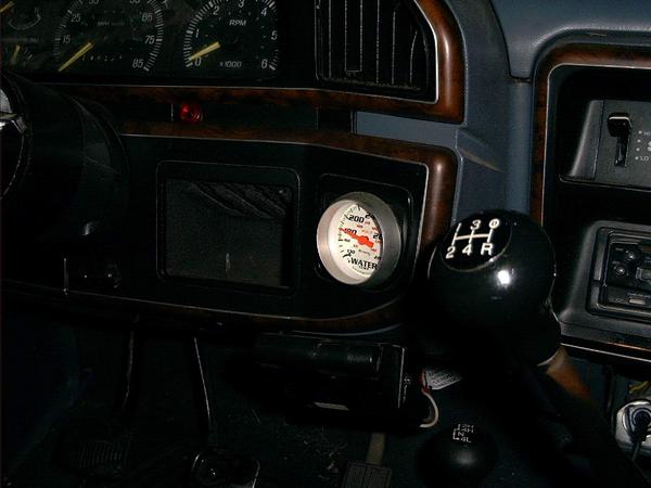
Finished look

Tube going through the firewall near the pedals

Back of the steering column trim
Finished look
Tube going through the firewall near the pedals
Last edited by Hunt4Fun; Nov 10, 2002 at 07:17 PM.
Thread Starter
|
Senior Member
Joined: Mar 2001
Posts: 418
Likes: 0
From: Indianapolis, IN, USA
More Pictures
Here are the remaining pictures in the engine compartment.
The hole in the firewall is above the round rubber piece.

Then one loop around the steering column to keep the tube away from the exhaust.

And then the Tee connector

98, let me know if you need other angles.
Hunt4Fun
The hole in the firewall is above the round rubber piece.
Then one loop around the steering column to keep the tube away from the exhaust.
And then the Tee connector
98, let me know if you need other angles.
Hunt4Fun

Technical Article Contributor

Joined: Dec 1997
Posts: 9,417
Likes: 11
From: Windsor,Ontario,Canada
Hunt,
Great pictures. I would change the routing of the plastic hose. Having it go around the steering shaft is dangerous. If it binds on the shaft while you are turning it could snap the tube and you will loose all your oil. You should also slit the rubber plug in the fire wall and let the hose go through the middle of it. It will rub against the metal and will for sure cut the tube over time. I would route it from the firewall to the frame along the frame towards the front then back over towards the sender. This will keep it away from the exhaust manifold. Allow enough slack so when the engine rocks it will not stretch the the tube. It looks like you used that white silicone tape for the connections on the T fitting. Nice touch. Can you share the Part numbers for the fittings?
Regards
Jean Marc Chartier
Last edited by JMC; Nov 10, 2002 at 10:14 PM.
Thread Starter
|
Senior Member
Joined: Mar 2001
Posts: 418
Likes: 0
From: Indianapolis, IN, USA
I agree, I'll reroute the tube
Frankly, I should have given the route of the tube some more thought. It's easy to disconnect on either end and do the rerouting. Probably easier to disconnect in the engine compartment. Nice that I can reach the T connector without even jacking up the truck. Just slide under and it's accessible.
Here's a picture of the two fittings:

Hope that helps. And thanks for the suggestions to reroute the tubes!!
Here's a picture of the two fittings:
Hope that helps. And thanks for the suggestions to reroute the tubes!!
Senior Member
Joined: Jul 2000
Posts: 5,116
Likes: 3
From: Houston, by way of every major city in America.
Yes, great pics!! Thank you very much! I didn't even know where the sending unit was to begin with,  . So, it's at the front of the engine on the drivers side, close to the motor mount? As far as the protection for the tubing, I wonder if you can buy the type of sheathing they use on the brake lines? That wire wrapped looking stuff? Even a wire loom could do a good enough job if it was kept away from the manifold? Aside from that maybe some cable clips?,,,,98
. So, it's at the front of the engine on the drivers side, close to the motor mount? As far as the protection for the tubing, I wonder if you can buy the type of sheathing they use on the brake lines? That wire wrapped looking stuff? Even a wire loom could do a good enough job if it was kept away from the manifold? Aside from that maybe some cable clips?,,,,98
Thread Starter
|
Senior Member
Joined: Mar 2001
Posts: 418
Likes: 0
From: Indianapolis, IN, USA
Start with the Oil Filter
On my 4.2, the sending unit is just above the oil filter. Find that, and the sending unit is easy to find. That helped me a lot.
I might drill out the hole in the firewall a little more and put a rubber grommet in it. That way I don't have to drill another hole, only enlarge the one that I have.
Hope to do that this week. I'll post more pictures when that is complete.
Hunt4Fun
I might drill out the hole in the firewall a little more and put a rubber grommet in it. That way I don't have to drill another hole, only enlarge the one that I have.
Hope to do that this week. I'll post more pictures when that is complete.
Hunt4Fun