Victor Reinz Head Gaskets: Any good?
#31
 10-11-2009, 04:44 AM


Join Date: Jul 2009
Location: Miami, FL
Posts: 250
Likes: 0
Received 0 Likes
on
0 Posts
Doing some google searching I came across this PDF on setting the timing on the 5.4.
http://ww2.justanswer.com/uploads/jm...ming_02_54.pdf
Just thought I'd share it to complement the walkthrough that DYNOTECH posted.
BTW: The guy who had posted this online suggested that you don't need the special tools if you remove the rockers so that the cams can freewheel. So just one more way to do this I guess.
- Erik
#32
10-11-2009, 08:31 PM

Senior Member
Join Date: May 2008
Location: Minnesota
Posts: 969
Likes: 0
Received 0 Likes
on
0 Posts
Or drain the lifters free of oil at the front and rear of the head? That will allow the cams to spin a little easier. That website you provided will work best for you if you have made the markings on the timing chains otherwise you need to follow Bluejays write-up. I am still having difficultys, but thanks to this forum, we'll git er' dun!
#33
10-11-2009, 08:48 PM


Or drain the lifters free of oil at the front and rear of the head? That will allow the cams to spin a little easier. That website you provided will work best for you if you have made the markings on the timing chains otherwise you need to follow Bluejays write-up. I am still having difficultys, but thanks to this forum, we'll git er' dun!
Bluejay posted it.

#34
10-11-2009, 08:52 PM
Doing some google searching I came across this PDF on setting the timing on the 5.4.
http://ww2.justanswer.com/uploads/jm...ming_02_54.pdf
Just thought I'd share it to complement the walkthrough that DYNOTECH posted.
BTW: The guy who had posted this online suggested that you don't need the special tools if you remove the rockers so that the cams can freewheel. So just one more way to do this I guess.
- Erik
http://ww2.justanswer.com/uploads/jm...ming_02_54.pdf
Just thought I'd share it to complement the walkthrough that DYNOTECH posted.
BTW: The guy who had posted this online suggested that you don't need the special tools if you remove the rockers so that the cams can freewheel. So just one more way to do this I guess.
- Erik
#35
10-11-2009, 09:05 PM

Senior Member
Join Date: Aug 2003
Location: Susquehanna Valley, pa.
Posts: 1,921
Likes: 0
Received 0 Likes
on
0 Posts
I removed my head with no problems. i just need to get the parts now.
I posted some pic in the thread i started.
https://www.f150online.com/forums/v8...lugs-cops.html
I posted some pic in the thread i started.
https://www.f150online.com/forums/v8...lugs-cops.html
#36
10-11-2009, 09:19 PM
Senior Member
Join Date: May 2008
Location: Minnesota
Posts: 969
Likes: 0
Received 0 Likes
on
0 Posts
#37
10-11-2009, 09:26 PM
Senior Member
Join Date: May 2008
Location: Minnesota
Posts: 969
Likes: 0
Received 0 Likes
on
0 Posts
#38
10-11-2009, 09:55 PM
Senior Member
Join Date: Aug 2003
Location: Susquehanna Valley, pa.
Posts: 1,921
Likes: 0
Received 0 Likes
on
0 Posts
When i marked it, it was 90 deg from the deck (straight up) and once the chain was removed it spun 90 deg clockwise as you look at it. I think this is why they recommend using the cam holding tool. No big deal to reposition it so the marks line back up for reassembly.
#39
10-12-2009, 02:11 PM

Doing some google searching I came across this PDF on setting the timing on the 5.4.
http://ww2.justanswer.com/uploads/jm...ming_02_54.pdf
Just thought I'd share it to complement the walkthrough that DYNOTECH posted.
BTW: The guy who had posted this online suggested that you don't need the special tools if you remove the rockers so that the cams can freewheel. So just one more way to do this I guess.
- Erik
http://ww2.justanswer.com/uploads/jm...ming_02_54.pdf
Just thought I'd share it to complement the walkthrough that DYNOTECH posted.
BTW: The guy who had posted this online suggested that you don't need the special tools if you remove the rockers so that the cams can freewheel. So just one more way to do this I guess.
- Erik
#40
10-12-2009, 05:27 PM
Join Date: Jul 2009
Location: Miami, FL
Posts: 250
Likes: 0
Received 0 Likes
on
0 Posts
-Edit - DYNOTECH are you sure that the 2v don't have two colored links on the cam gear side of the chain? Because from looking at lees99f150's thread he had to color two chain links on the cam gear side of things because the cam gear mark fell between two links on the chain. Just want to clear that up and learn as much as I can for when I change the head gasket in the near future.
- Erik
- Erik
Last edited by scruffy; 10-12-2009 at 05:39 PM.
#41
10-12-2009, 09:13 PM
Senior Member
Join Date: May 2008
Location: Minnesota
Posts: 969
Likes: 0
Received 0 Likes
on
0 Posts
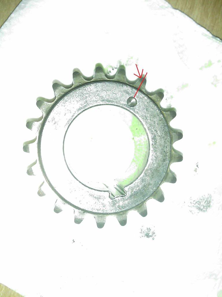
So i found another place with valuable information reguarding the links. It says, if you cannot find the copper links, to do this, for 5.4 and 6.8 engines in reply to a guy that broke a timing chain on his 1997 f150 5.4
http://www.justanswer.com/view_image...4/7924FG92.gif
The Q&A is at http://www.justanswer.com/questions/...e-1997-f-150-5
click, "READ MORE" in orange.
Now, am i lining the link at the one end of the chain to the punched "dimple" on the crankshaft timing gear, there is only 1 punch. Is this correct?
#42
10-12-2009, 09:26 PM
So i found another place with valuable information reguarding the links. It says, if you cannot find the copper links, to do this, for 5.4 and 6.8 engines in reply to a guy that broke a timing chain on his 1997 f150 5.4
http://www.justanswer.com/view_image...4/7924FG92.gif
The Q&A is at http://www.justanswer.com/questions/...e-1997-f-150-5
click, "READ MORE" in orange.
Now, am i lining the link at the one end of the chain to the punched "dimple" on the crankshaft timing gear, there is only 1 punch. Is this correct?
http://www.justanswer.com/view_image...4/7924FG92.gif
The Q&A is at http://www.justanswer.com/questions/...e-1997-f-150-5
click, "READ MORE" in orange.
Now, am i lining the link at the one end of the chain to the punched "dimple" on the crankshaft timing gear, there is only 1 punch. Is this correct?
#43
10-12-2009, 09:42 PM
Senior Member
Join Date: May 2008
Location: Minnesota
Posts: 969
Likes: 0
Received 0 Likes
on
0 Posts
#44
10-12-2009, 09:45 PM
-Edit - DYNOTECH are you sure that the 2v don't have two colored links on the cam gear side of the chain? Because from looking at lees99f150's thread he had to color two chain links on the cam gear side of things because the cam gear mark fell between two links on the chain. Just want to clear that up and learn as much as I can for when I change the head gasket in the near future.
- Erik
- Erik
Last edited by DYNOTECH; 10-12-2009 at 09:49 PM.