
02' F250 EGR valve location ???


Thread Starter
|
Member
Joined: Jul 2008
Posts: 59
Likes: 0
From: Anchorage, Ak
02' F250 EGR valve location ???
Well I searched the whole trucks engine bay and never found the EGR.
Where the hell is it in this truck? I don't even see an EGR tube coming off the exhaust....
2002 F250 SD 5.4L
(I did read that the V10 don't have EGR's, is this true w/ the 5.4L f250 as well?)
Partstrain.com has the part for some reason....
http://www2.partstrain.com/store/?Nt...6%204294967263
Where the hell is it in this truck? I don't even see an EGR tube coming off the exhaust....
2002 F250 SD 5.4L
(I did read that the V10 don't have EGR's, is this true w/ the 5.4L f250 as well?)
Partstrain.com has the part for some reason....
http://www2.partstrain.com/store/?Nt...6%204294967263

Technical Article Contributor
Joined: Oct 2005
Posts: 25,641
Likes: 19
From: MI
Hell , you can't miss it, that's impossible...
Unless someone took it off or you don't know what your looking for~ Idunnooo.
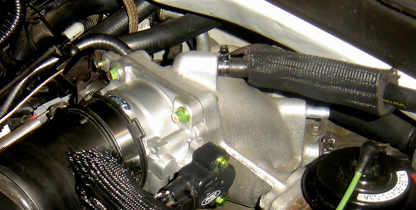
Here's mine, lower right hand corner -
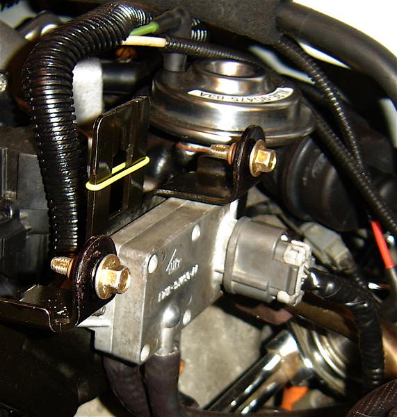
A close up of another one of mine
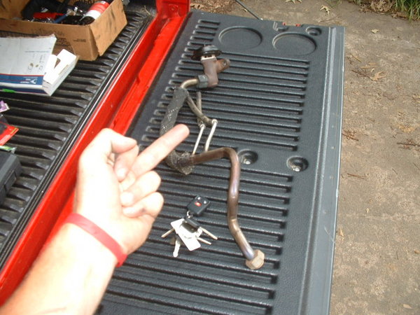
Here's all of it -
Unless someone took it off or you don't know what your looking for~ Idunnooo.
Here's mine, lower right hand corner -
A close up of another one of mine
Here's all of it -
Last edited by jbrew; Aug 2, 2008 at 06:13 PM.
Thread Starter
|
Member
Joined: Jul 2008
Posts: 59
Likes: 0
From: Anchorage, Ak
No I know what I'm looking for...
I'm not new to cars, just new to ford trucks.
The sensor and the egr valve are non-existent on my truck.
I checked out both manifolds & downpipes and there is no spot for a EGR hose anywhere.
Keep in mind this is a F250 SD
I'm not new to cars, just new to ford trucks.
The sensor and the egr valve are non-existent on my truck.
I checked out both manifolds & downpipes and there is no spot for a EGR hose anywhere.
Keep in mind this is a F250 SD
Technical Article Contributor
Joined: Oct 2005
Posts: 25,641
Likes: 19
From: MI
Keep in mind - A 5.4L is a 5.4L in these trucks, it's identical to the F150 5.4L - Shoot even the lightnings have a EGR valve. If it doesn't exist , than someone removed it ...- Period.
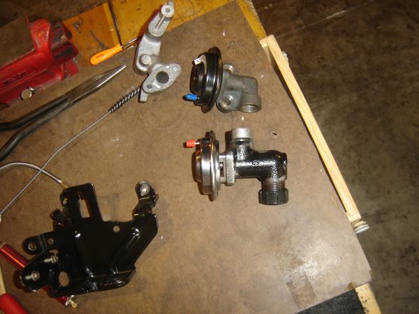
BTW - The EGR valve pictured in the link you posted is actually a 4.6L valve
- There just generalizing using that picture, the 5four valve is quite a bit larger than that. It's not a hose , it's a pipe.. Drivers side back of the manifold - there is a nipple thereTrust me , you have or HAD an EGR on that one, here's the difference 4.6 and 5.4 pictured -
Last edited by jbrew; Aug 2, 2008 at 11:19 PM.
Thread Starter
|
Member
Joined: Jul 2008
Posts: 59
Likes: 0
From: Anchorage, Ak
Ok, so where is the pipe supposed to connect to in the exhaust?
Because there is no threaded hole anywhere on the manifold or downpipes.
No EGR, no sensor, & no pipe anywhere...
Where does the egr pipe connect to on your truck?
Because there is no threaded hole anywhere on the manifold or downpipes.
No EGR, no sensor, & no pipe anywhere...
Where does the egr pipe connect to on your truck?
Thread Starter
|
Member
Joined: Jul 2008
Posts: 59
Likes: 0
From: Anchorage, Ak
Ok, I just checked the emmisions Vacuum hose routing sticker on the valve cover....
No egr or dpfe is listed on that sticker.
WTF!?
I also just noticed the angles the throttle body comes off the manifold are different.
The straight piece on my intake tube runs exactly over where your dpfe & egr sit.
My throttle body comes out at the same angle as the V10, uses same intake tube as well. Except mine says Triton V8 instead of V10...
Last edited by Snowmansdsm09; Aug 3, 2008 at 12:28 AM.
Thread Starter
|
Member
Joined: Jul 2008
Posts: 59
Likes: 0
From: Anchorage, Ak
My engine bay is exactly the same setup as these v10s.
Only difference I see is that manifold is aluminum, mine is plastic.
The v10 has the dual port throttle body, while mine has the single...
It looks like a dpfe sensor in the first picture here located by the hoses coming off the intake tube.
Then if you look at the next picture you can trace those hoses down to the drivers side manifold where there must be a port.
I for one, have none of that. No pre-existing port thats been covered... nothing.
The last link is a F250 5.4l
http://image.motortrend.com/f/roadte...kup_engine.jpg
http://www.sporttruckdirect.com/Pics...0_inst_Big.jpg
http://www.ecoastauto.com/images/ford/d332/1.jpg
Trending Topics
Technical Article Contributor
Joined: Oct 2005
Posts: 25,641
Likes: 19
From: MI
Wow! Snowman, what year truck is that last pick. I've never seen a set-up like that on the 97-03 models. You have an 02 right? Is yours the same set up ? Maybe I'm wrong 
Don't tell anyone..
Don't tell anyone..
Thread Starter
|
Member
Joined: Jul 2008
Posts: 59
Likes: 0
From: Anchorage, Ak
I don't know what year that truck is in the last link, but that is exactly my setup.
2002 F250 SD 5.4L
I want to know how the hell they got away with no EGR on this truck. No wonder I ping under load... & my gas mileage is 12mpg highway.
I must have the 'Oil Company Edition'
2002 F250 SD 5.4L
I want to know how the hell they got away with no EGR on this truck. No wonder I ping under load... & my gas mileage is 12mpg highway.
I must have the 'Oil Company Edition'
Technical Article Contributor
Joined: Oct 2005
Posts: 25,641
Likes: 19
From: MI
No we have oil company trucks / Bp purchased them I guess, but they say Alliant Energy on side w/US dot number lol. But the most puzzling part - We just got em last month 12 4x4's and their older models w/7.3L's . There's two w/13,000 miles but the others have between 3 - 8000 miles. Where in the hell did they find these!!! What sucks is , their all Burgundy , every stinking one of them.
Anyway, yea - I have never seen a set-up like yours.
If you getting that kind of mileage on the highway -
1. Update the O2's w/OEM Bosch parts only.
2. Fuel Filter, PCV valve
3. Make sure you have Motorcraft plugs in there.
4. Clean the MAF sensor
5. Clean the throttle body and elbow.
The O2's and MAF Sensor have allot to do with mileage. They need to be healthy and in good shape. Also, the air filter has to be at it's best.
Last edited by jbrew; Aug 3, 2008 at 02:30 PM.
Technical Article Contributor
Joined: Oct 2005
Posts: 25,641
Likes: 19
From: MI
Well, I looked it up on the 2002 Ford service DVD.
F250 SD 5.4L . It shows this -

Item Description
1 — Fuel pressure regulator (part of 9E498)
2 — Exhaust gas recirculation (EGR) vacuum regulator solenoid (part of 9E498)
3 — EGR valve (part of 9E498)
4 — Vacuum source (part of 9E498)
5 — Vacuum management valve (part of 9E498)
6 — To vacuum reservoir
F250 SD 5.4L . It shows this -
Item Description
1 — Fuel pressure regulator (part of 9E498)
2 — Exhaust gas recirculation (EGR) vacuum regulator solenoid (part of 9E498)
3 — EGR valve (part of 9E498)
4 — Vacuum source (part of 9E498)
5 — Vacuum management valve (part of 9E498)
6 — To vacuum reservoir
Last edited by jbrew; Aug 3, 2008 at 02:57 PM.
Thread Starter
|
Member
Joined: Jul 2008
Posts: 59
Likes: 0
From: Anchorage, Ak
1. Update the O2's w/OEM Bosch parts only.
2. Fuel Filter - DONE
2.5 PCV valve
3. Make sure you have Motorcraft plugs in there -DONE
4. Clean the MAF sensor - DONE
5. Clean the throttle body and elbow. - DONE
I should probably do my O2's next...
2. Fuel Filter - DONE
2.5 PCV valve
3. Make sure you have Motorcraft plugs in there -DONE
4. Clean the MAF sensor - DONE
5. Clean the throttle body and elbow. - DONE
I should probably do my O2's next...
Thread Starter
|
Member
Joined: Jul 2008
Posts: 59
Likes: 0
From: Anchorage, Ak
In the bottom picture tat you posed...
2 & 3 not there.
I had the throttle body and elbow off about 2 weeks ago and was amazed how clean the elbow was.
There was no EGR valve or solenoid. No pre-existing spot that was covered by a blockoff plate. Just clean molded plastic elbow thats it.
I'm gonna bust out the camera here in a second, people are gonna think I'm crazy.
Technical Article Contributor
Joined: Oct 2005
Posts: 25,641
Likes: 19
From: MI
I found it. Damn! - Yea, never seen one like that before. So you have an electric EGR valve, you just can't see it's covered. It says with this system you don't have a DPF sensor or tube assembly.

Last edited by jbrew; Aug 3, 2008 at 04:43 PM.
Technical Article Contributor
Joined: Oct 2005
Posts: 25,641
Likes: 19
From: MI
Here's the data -
Electric Exhaust Gas Recirculation (EEGR) System Monitor
The Electric EGR System Monitor is an on-board strategy designed to test the integrity and flow characteristics of the EGR system. The monitor is activated during EGR system operation and after certain base engine conditions are satisfied. Input from the ECT or CHT, IAT, TP, CPS, MAF, and MAP sensors is required to activate the EGR System Monitor. Once activated, the EGR System Monitor will perform each of the tests described below during the engine modes and conditions indicated. Some of the EGR System Monitor tests are also performed during on demand self-test
The Stepper Motor EGR Monitor consists of an electrical and functional test that checks the stepper motor and the EGR system for proper flow. The PCM controls the EGR valve by commanding from 0 to 52 discreet increments or "steps" to get the valve from fully closed to fully open. The stepper motor electrical test is a continuous check of the four electric stepper motor coils and circuits to the PCM. A malfunction is indicated if an open circuit, short to power, or short to ground has occurred in one or more of the stepper motor coils / circuits for a calibrated period of time. If a malfunction has been detected, the EGR system will be disabled, setting the KOER, and Cont. P0403 DTC. Additional monitoring will be suspended for the remainder of the driving cycle, or until the next engine startup.
After the vehicle has warmed up and normal EGR rates are being commanded by the PCM, the EGR flow check is performed. The flow test is performed once per drive-cycle when a minimum amount of EGR is requested and the remaining entry conditions required to initiate the test are satisfied. If a malfunction is detected, the EGR system as well as the EGR monitor is disabled until the next engine startup.
The EGR flow test is done by observing the behavior of two different values of MAP - the analog MAP sensor reading, and inferred MAP (MAP calculated from the Mass Air Flow Sensor, throttle position, rpm, etc.). During normal, steady-state operating conditions, EGR is intrusively commanded ON to a specified percentage. Then, EGR is commanded OFF. If the EGR system is working properly, there is a significant difference in both the observed and the calculated values of MAP, between the EGR-ON and the EGR-OFF states.
When the flow test entry conditions have been satisfied, EGR is commanded to flow at a calibrated test rate (about 10%). At this time, the value of MAP is recorded (EGR-ON MAP). The value of inferred MAP EGR-ON IMAP is also recorded. Next the EGR is commanded off (0%). Again, the value of MAP is recorded (EGR-OFF MAP). The value of EGR-OFF IMAP is also recorded. Typically, seven such ON/OFF samples are taken. After all the samples have been taken, the average EGR-ON MAP, EGR-ON IMAP, EGR-OFF MAP and EGR-OFF IMAP values are stored.
Next, the differences between the EGR-ON and EGR-OFF values are calculated:
MAP-delta = EGR-ON MAP � EGR-OFF MAP (analog MAP)
IMAP-delta = EGR-ON IMAP � EGR-OFF IMAP (inferred MAP)
If the sum of MAP-delta and IMAP-delta exceeds a maximum threshold or falls below a minimum threshold, a P0400 (high or low flow malfunction) is registered.
As an additional check, if the EGR-ON MAP exceeds a maximum threshold (BARO - a calibrated value), a P0400 low flow malfunction is registered. This check is performed to detect reduced EGR flow on systems where the MAP pickup point is not located in the intake manifold, but is located just upstream of the EGR valve in the EGR delivery tube.
Note: BARO is inferred at engine startup using the KOEO MAP sensor reading. It is updated during high, part-throttle or high rpm engine operation.
If the inferred ambient temperature is less than 20� F (-7� C), greater than 130� F (54� C), or the altitude is greater than 8,000 feet (BARO <22.5 " Hg), the EGR flow test cannot be reliably done. In these conditions, the EGR flow test is suspended and a timer starts to accumulate the time in these conditions. If the vehicle leaves these extreme conditions, the timer starts decrementing, and if conditions permit, will attempt to complete the EGR flow monitor. If the timer reaches 500 seconds, the EGR flow test is disabled for the remainder of the current driving cycle and the EGR Monitor I/M Readiness bit will be set to a "ready" condition.
A DTC of P1408, like the P0400, will indicate a EGR flow failure (outside the minimum or maximum limits) but is only set during the KOER self test. The P0400 and P0403 are MIL codes, the P1408 is a non-MIL code.