

How To: 5.4 Engine Assembly (Photos)


Thread Starter
|
Senior Member
Joined: May 2001
Posts: 3,300
Likes: 0
From: Richmond, VA, USA
you are now ready to install your rings. there are 3 of them, well 5 really, but the bottom one which is the oil scraper or oil control ring is made up of 3 seperate rings.
you install rings starting at the bottom of the piston first so we'll start with the oil control ring. as I said it is three pieces, but the center expander or tensioner piece has to go on first as the other two fit over top of it's edges. be sure that the ends but up against each other on this one, BUT DO NOT OVERLAP! you can see where the ends of this ring are directly above the wrist pin hole in the piston.
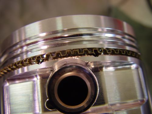
now you can install the other two parts of the oil ring. one on top and one on bottom of the expander like this:
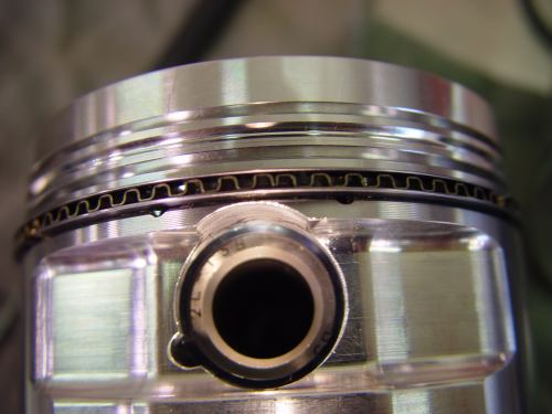
now you are ready to install the second ring and then the top compression ring.
using a ring installer tool is supposed to be easier on the rings, but it's definately easier on your fingertips.
first in stall the second ring, it is cast or ductile iron and has a grey/black finish on this particular set.
you install rings starting at the bottom of the piston first so we'll start with the oil control ring. as I said it is three pieces, but the center expander or tensioner piece has to go on first as the other two fit over top of it's edges. be sure that the ends but up against each other on this one, BUT DO NOT OVERLAP! you can see where the ends of this ring are directly above the wrist pin hole in the piston.
now you can install the other two parts of the oil ring. one on top and one on bottom of the expander like this:
now you are ready to install the second ring and then the top compression ring.
using a ring installer tool is supposed to be easier on the rings, but it's definately easier on your fingertips.
first in stall the second ring, it is cast or ductile iron and has a grey/black finish on this particular set.
Last edited by superfords; Feb 28, 2004 at 10:10 PM.
Thread Starter
|
Senior Member
Joined: May 2001
Posts: 3,300
Likes: 0
From: Richmond, VA, USA
then install the top ring using the same method, the top ring on this set is moly (not chromemoly, cause there is no such kind of ring) which has a light grey or silver edge(hard to see in this pic). that's how you differentiate the top ring from the second ring. the moly ring has a groove around it's circumference that is filled with moly? whatever that is? and it is supposed to seal better than standard rings. now your piston looks something like this:

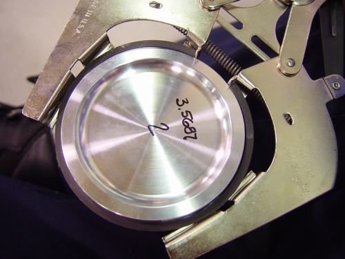
now follow your RING MANUFACTURER's (or Tuner's, or favorite engine builder's) instructions for specific location of the gaps around the piston when you install the piston into the bore. ex. generally, the top and second ring gaps are installed on opposite sides of the piston. also on these oil rings, there were specific instructions as to where the gap on EACH of the 3 parts of the oil control ring was to be placed!
ALSO VERY IMPORTANT. your rings may be beveled on one side, or have ledges on the outside edge, or have words like "TOP" or "UP" or some may have a tiny "dot" or dimple on one side. carefully follow the ring manufacturers instructions, because in many cases the rings are directional and are designed to have one side or the other facing the top of the piston.
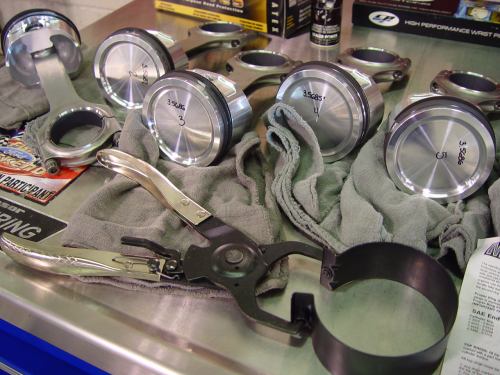
now do that to all of your pistons and you'll have this:
and it is supposed to seal better than standard rings. now your piston looks something like this: now follow your RING MANUFACTURER's (or Tuner's, or favorite engine builder's) instructions for specific location of the gaps around the piston when you install the piston into the bore. ex. generally, the top and second ring gaps are installed on opposite sides of the piston. also on these oil rings, there were specific instructions as to where the gap on EACH of the 3 parts of the oil control ring was to be placed!
ALSO VERY IMPORTANT. your rings may be beveled on one side, or have ledges on the outside edge, or have words like "TOP" or "UP" or some may have a tiny "dot" or dimple on one side. carefully follow the ring manufacturers instructions, because in many cases the rings are directional and are designed to have one side or the other facing the top of the piston.
now do that to all of your pistons and you'll have this:
Last edited by superfords; Feb 29, 2004 at 07:52 AM.
Thread Starter
|
Senior Member
Joined: May 2001
Posts: 3,300
Likes: 0
From: Richmond, VA, USA
you have already determined which piston is going into each bore by measuring each piston and then measuring each bore and select fitting each one for the optimal clearance. you have also matched the piston ring end gap to each bore and HOPEFULLY you've now installed the correct rings onto the piston that is going into the hole that you filed the rings to fit!
you are now ready to install the piston/rod assemblies into each bore.
lubricate the cylinder bore and lubricate the rings and side of piston and also your installer tool with oil.

then carefully slide the installer tool down over the ring set and piston.

then tighten your ring compressor tool on the piston. there are several different types of piston/ring installer tools available. and you can begin to lower the assembly down into the cylinder bore.
many people like to use a rod installer safety tools(can't remember the correct name right now ). they go onto the bottom of the rod into the bolt holes or screw into the rod and guide the rod down the bore and protect the cylinder walls and crankshaft journal from being scratched.
you are now ready to install the piston/rod assemblies into each bore.
lubricate the cylinder bore and lubricate the rings and side of piston and also your installer tool with oil.
then carefully slide the installer tool down over the ring set and piston.
then tighten your ring compressor tool on the piston. there are several different types of piston/ring installer tools available. and you can begin to lower the assembly down into the cylinder bore.
many people like to use a rod installer safety tools(can't remember the correct name right now
). they go onto the bottom of the rod into the bolt holes or screw into the rod and guide the rod down the bore and protect the cylinder walls and crankshaft journal from being scratched.


Thread Starter
|
Senior Member
Joined: May 2001
Posts: 3,300
Likes: 0
From: Richmond, VA, USA
now slowly lower the rod/piston assembly down into it's bore:

when the piston skirts get down into the bore and the installer tool hits the deck then you should make sure that the installer tool is square and has the proper tension. and you can then GENTLY tap the piston into place. if you feel it stop, then STOP tapping, re oil and start over! you can easily crack one of the delicate rings if it isn't compressed or lubed enough and it gets hung on the top edge of the bore instead of sliding down into the bore.

sorry I don't have more pictures of this very important part of the assembly, but my photographer was really supposed to be WORKING elsewhere in the shop instead of messing around with me. and it's hard enough to do this part of the job with all of the oil and assembly lube and slippery parts involved, but then try fumbling with an expensive camera and something is bound to go wrong.
anyway, once all the rings have cleared the deck and the piston has been inserted, you can slowly push or tap it down until the big end of the rod gets close to the crank journal. you'll need to turn the crank in between installing each piston/rod in order to align each journal with whichever cylinder bore you are installing at that time.
when the rod gets close to the crank, you make sure that the upper half of the rod bearing is still properly located after all of the tapping with the hammer and (if you didn't already do this) apply plenty of assembly lube to the bearing surface. now slowly push down on the piston as you guide the rod and bearing down onto the crankshaft journal. once it's seated on the crank, you can apply assembly lube to the lower rod bearing half which you previously installed into the rod cap, and then put it into place and tighten snug your rod bolts by hand. as always, if using arp rod bolts (or cap screws as some folks call them) then you need to apply some moly lube or motor oil to the underside of the bolt head and to the threads of the bolt.
when the piston skirts get down into the bore and the installer tool hits the deck then you should make sure that the installer tool is square and has the proper tension. and you can then GENTLY tap the piston into place. if you feel it stop, then STOP tapping, re oil and start over! you can easily crack one of the delicate rings if it isn't compressed or lubed enough and it gets hung on the top edge of the bore instead of sliding down into the bore.
sorry I don't have more pictures of this very important part of the assembly, but my photographer was really supposed to be WORKING elsewhere in the shop
instead of messing around with me. and it's hard enough to do this part of the job with all of the oil and assembly lube and slippery parts involved, but then try fumbling with an expensive camera and something is bound to go wrong.anyway, once all the rings have cleared the deck and the piston has been inserted, you can slowly push or tap it down until the big end of the rod gets close to the crank journal. you'll need to turn the crank in between installing each piston/rod in order to align each journal with whichever cylinder bore you are installing at that time.
when the rod gets close to the crank, you make sure that the upper half of the rod bearing is still properly located after all of the tapping with the hammer and (if you didn't already do this) apply plenty of assembly lube to the bearing surface. now slowly push down on the piston as you guide the rod and bearing down onto the crankshaft journal. once it's seated on the crank, you can apply assembly lube to the lower rod bearing half which you previously installed into the rod cap, and then put it into place and tighten snug your rod bolts by hand. as always, if using arp rod bolts (or cap screws as some folks call them) then you need to apply some moly lube or motor oil to the underside of the bolt head and to the threads of the bolt.
Last edited by superfords; Feb 28, 2004 at 10:37 PM.
Thread Starter
|
Senior Member
Joined: May 2001
Posts: 3,300
Likes: 0
From: Richmond, VA, USA
after you've installed all 4 cylinders on one bank of the block, it'll look like this:

now you can rotate your block on the engine stand and go to work on the other side!
same procedure only slightly more care needs to be taken with aligning the rods because now the bearing end of the rod has to fit inbetween the counterweight and the other previously installed connecting rod.
now all 8 pistons and rods are installed!

now the bottom of your short block looks like this and you are ready for the final torquing.

now you can rotate your block on the engine stand and go to work on the other side!
same procedure only slightly more care needs to be taken with aligning the rods because now the bearing end of the rod has to fit inbetween the counterweight and the other previously installed connecting rod.
now all 8 pistons and rods are installed!
now the bottom of your short block looks like this and you are ready for the final torquing.
Thread Starter
|
Senior Member
Joined: May 2001
Posts: 3,300
Likes: 0
From: Richmond, VA, USA
here is the torque sequence:

the arp bolts are 45-49 ftlbs (depending on who you ask) w/ moly lube.
the next step is to install your oil pump, but I'm going to save that for another day.
so I just reinstalled my head studs and bagged it up for safe keeping till next time.


that's all for today. it was too nice outside to stay in the shop any longer.
stay tuned!
later,
chris
the arp bolts are 45-49 ftlbs (depending on who you ask) w/ moly lube.
the next step is to install your oil pump, but I'm going to save that for another day.
so I just reinstalled my head studs and bagged it up for safe keeping till next time.
that's all for today. it was too nice outside to stay in the shop any longer.
stay tuned!
later,
chris


