
Aux Reverse Lighting - Mod


Thread Starter
|
Member
Joined: Nov 2012
Posts: 31
Likes: 0
From: Rochester NY
Aux Reverse Lighting - Mod
I could not decide if I wanted the switch for my auxiliary reverse lights in the cab (on-off-on switch) or in the bed/bumper (waterproof on-off switch) as both have times where they would be more convenient. I have the following hybrid plan and am looking for feedback if it will work. I can not find any threads that model this exact scenario. Truck is a 2012 F-150 STX Ext Cab. Lights : Tuff LED Lights 2 X 4" Inch Square 27watt LED Work Lamp Light 1550 Lumen
Cab Switch (On 1 - On with Factory Reverse Lights ; Off - No Aux Reverse Lights (daytime use or if someone is behind me as these will be bright) ; On 2 On manually from cab)
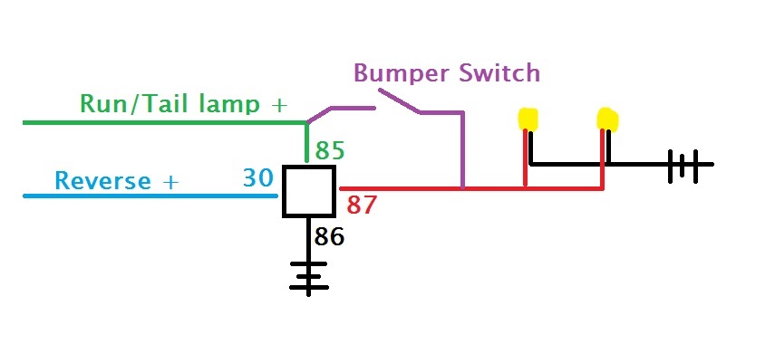
L1 from Reverse triggered Lead (fuse #15 in cab)
C to Pin 86 of Relay
L2 from Delay Accessory Lead (fuse #38 in cab)
Bumper Switch
S to red wire of Aux Light
+ from pin 87A of Relay
Relay
86 from C of cab switch
85 Spliced to Truck Ground Wire
30 from truck battery with inline 15A fuse
87A to Bumper switch
87 to red wire of Aux Light
Aux Light
Red wire from Relay Pin 87 and from Bumber Switch (Relay Pin 87A)
Is it OK to have red wire of Aux light connected to both pins 87 and 87A (when bumper switch is open) as these two terminals of the relay should never be active simultaneously (in my limited understanding of relays)?
Cab Switch (On 1 - On with Factory Reverse Lights ; Off - No Aux Reverse Lights (daytime use or if someone is behind me as these will be bright) ; On 2 On manually from cab)
L1 from Reverse triggered Lead (fuse #15 in cab)
C to Pin 86 of Relay
L2 from Delay Accessory Lead (fuse #38 in cab)
Bumper Switch
S to red wire of Aux Light
+ from pin 87A of Relay
Relay
86 from C of cab switch
85 Spliced to Truck Ground Wire
30 from truck battery with inline 15A fuse
87A to Bumper switch
87 to red wire of Aux Light
Aux Light
Red wire from Relay Pin 87 and from Bumber Switch (Relay Pin 87A)
Is it OK to have red wire of Aux light connected to both pins 87 and 87A (when bumper switch is open) as these two terminals of the relay should never be active simultaneously (in my limited understanding of relays)?
Thread Starter
|
Member
Joined: Nov 2012
Posts: 31
Likes: 0
From: Rochester NY
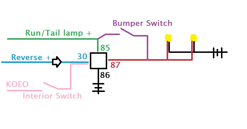
Hard to tell what is simple with this as it all confuses me! Tks for the offer. From the cab I want ability for lights to come on in reverse, lights to come on manually (but protected from being left on by connecting to a source that requires key in ignition) and possibility of aux lights being disabled so they do not come on in reverse. Then would like ability to switch lights on using a rear bumper switch that will function independent and regardless of position of cab switch.
Posted from F150online.com App for Android
Posted from F150online.com App for Android
Thread Starter
|
Member
Joined: Nov 2012
Posts: 31
Likes: 0
From: Rochester NY
As I see it, options for power sources are cabin fuse panel, under hood fuse panel and towing wire harness in rear if truck. Willing to run wires and locate relay any that seems most convenient.
Posted from F150online.com App for Android
Posted from F150online.com App for Android
Global Moderator &
Senior Member
Senior Member

Joined: Aug 2005
Posts: 21,337
Likes: 159
From: DFW
Well the way I setup my reverse fog lights (no switches) the truck has to be in R and have the running/headlights.
Effectively using the headlight switch as my master switch.....
I'll get going on the diagram
Effectively using the headlight switch as my master switch.....
I'll get going on the diagram
Last edited by Patman; Jun 30, 2013 at 11:20 PM.
Global Moderator &
Senior Member
Senior Member
Joined: Aug 2005
Posts: 21,337
Likes: 159
From: DFW
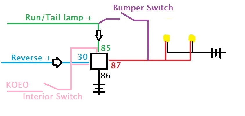
If you set it up like mine this would be the most simple way to do it. I've drawn in the bumper switch like you'd like.
If you don't want to have the running lights on to be able to use the bumper switch, just find your own power source. I just figured that way you'd be less likely to leave them on if they are tied to the headlight circuit/switch.
If you don't want to have the running lights on to be able to use the bumper switch, just find your own power source. I just figured that way you'd be less likely to leave them on if they are tied to the headlight circuit/switch.
Global Moderator &
Senior Member
Senior Member
Joined: Aug 2005
Posts: 21,337
Likes: 159
From: DFW
If you're dead set on having a dedicated switch, I'd recommend still using the headlight switch as a control, but not necissary if you're using KOEO + (Just remember to use a large diode between the relay and where you tapped the reverse lights. You don't want to back feed the reverse lights.
Trending Topics
Thread Starter
|
Member
Joined: Nov 2012
Posts: 31
Likes: 0
From: Rochester NY
Patman , these are very helpful-Thank You for taking the time to do this! I could be wrong but isn't there a problem if the relay kicks on pin 87 when the bumper switch is in the OPEN position (I am working behind the truck with the switch on and need to back up a few feet to my trailer). Would this result in two concurrent sources to the aux lights and a blown fuse/lights? This is why I was attempting to use a 5 pin relay so that pins 87 and 87A would never overlap as 87A would only pass current to the switch when 87 was closed.

Technical Article Contributor
Joined: Jun 2002
Posts: 10,511
Likes: 10
From: Under the flightpath of old ORD 22R
The best I have so far is the 2 switches either turns them on or off.
2 SPDT switches, no center off function.

The power source is what every you choose ( hot in run only, hot in assy / run, etc ).
Hard to tell by the description if you are looking for a "all off" type of function, where they won't turn on at all.
The inclusion of reverse has me, but I am not one to use diodes tied to the factory wiring.
2 SPDT switches, no center off function.
The power source is what every you choose ( hot in run only, hot in assy / run, etc ).
Hard to tell by the description if you are looking for a "all off" type of function, where they won't turn on at all.
The inclusion of reverse has me, but I am not one to use diodes tied to the factory wiring.
Global Moderator &
Senior Member
Senior Member
Joined: Aug 2005
Posts: 21,337
Likes: 159
From: DFW
Patman , these are very helpful-Thank You for taking the time to do this! I could be wrong but isn't there a problem if the relay kicks on pin 87 when the bumper switch is in the OPEN position (I am working behind the truck with the switch on and need to back up a few feet to my trailer). Would this result in two concurrent sources to the aux lights and a blown fuse/lights? This is why I was attempting to use a 5 pin relay so that pins 87 and 87A would never overlap as 87A would only pass current to the switch when 87 was closed.
Thread Starter
|
Member
Joined: Nov 2012
Posts: 31
Likes: 0
From: Rochester NY
My original design was based on using the electrical connections to my switches as triggers not as pass through sources to the lights. I have read in a few other posts to not use the Reverse circuit or the Run/Tail circuit for these aux lights as it may overload the circuit. Thus, Pin 30 was a dedicated 15 amp circuit just for these lights. Thoughts.
Technical Article Contributor
Joined: Jun 2002
Posts: 10,511
Likes: 10
From: Under the flightpath of old ORD 22R
On the older MY trucks, the reverse lamp circuit cannot take an additional 2 A of load, the lights to not come to full brightness.
The 2011 you have the FET that controls the truck's reverse lamps, so if you add any load to this, it might turn the FET off ( thinking it is a overload issue ).
The reverse circuit you would need to use is the 7 pin trailer tow adapter.
- This is driven by a relay.
The other thing, is you would need a large enough switch, as not to create an inline resistance to the circuit ( you would want to go with a 20A+ switch with beefy enough contacts ).
So far the only way I have come up with to add the reverse in addition to the dual switch, is another relay.
- I don't like installing diodes to the factory wiring. I go the mechanical isolation route.
Technical Article Contributor
Joined: Jun 2002
Posts: 10,511
Likes: 10
From: Under the flightpath of old ORD 22R
- The post was not; modify the factory wiring.
The diagrams above, you have a KOEO circuit powering the the lamps through a switch, and to the relay ( both coil and common terminals ) as well as a reverse circuit powering the lights on the common terminal and a switch powering the lamps directly, bypassing the relay.
- That is not a mechanical isolation as I posted.