
Chose wrong hot wire for Ait Lift air compressor hookup?


Thread Starter
|
Junior Member
Joined: May 2007
Posts: 5
Likes: 0
From: Anaheim, CA
Chose wrong hot wire for Air Lift air compressor hookup?
I installed an Air Lift compressor over the weekend. I was looking for a wire that was only hot with the key on, and when I pulled up the cover over the driver's side wire channel, I found a wire that is yellow with a green stripe that is about 10 gage and came on with the key. I tapped in to that and all was well until this morning...now the circuit is dead and I am not sure what that wire was for. Everything seems to work (windows, lights, etc.) except the compressor and likely whatever that wire feed is for. If anyone can help me to first identify what the yellow w/green stripe wire is for AND can tell me a better wire to tap into for the compressor hookup, I would appreciate it.
Last edited by jimireb; Jul 6, 2009 at 01:09 PM. Reason: Fixed post title, clarified wire location

Senior Member
Joined: Jun 2007
Posts: 361
Likes: 0
Don't know what the wire is for but most likely over loaded it and blew fuse. Look in owners manual. It should identify circuits in fuse box.
Something like that should have a dedicated circuit with fuse protection. That way you do not have these types of problems. I would say the air lift compressor probably pulls 10-15 amps easily. Add that to an existing circuit and poof!
Something like that should have a dedicated circuit with fuse protection. That way you do not have these types of problems. I would say the air lift compressor probably pulls 10-15 amps easily. Add that to an existing circuit and poof!
Thread Starter
|
Junior Member
Joined: May 2007
Posts: 5
Likes: 0
From: Anaheim, CA
FM, the circuit is fused (15a inline comes with the compressor) but they (Air Lift) say on their instructions to have the compressor tied to an "ignition on" circuit to prevent the compressor from kicking on all the time from the low pressure switch. I have open circuits on the fuse panel I could have tied into but thought I was doing the right thing with the circuit I found. Any suggestions how to tie this in tie this in to a circuit that comes on with ignition? Or are you recommending that I put in a separate circuit and switch it myself?
And thanks for the reply....I SHOULD have known better than to grab that wire without tracking it first!
And thanks for the reply....I SHOULD have known better than to grab that wire without tracking it first!
Last edited by jimireb; Jul 6, 2009 at 01:11 PM.
Senior Member
Joined: Jun 2007
Posts: 361
Likes: 0
Thats good that the compressor has a fused power line. If the instructions told you to tie into another circuit...my bad. BUT...I am no professional BUT I believe especially since it has a fused power line to create a new circuit. In this case you DO want the circuit to be hot ONLY when key is on due to the compressor cycling.
Find a circuit that is not super critical like wipers, radio, power seats, etc. That way if something ever does happen you won't be without something you need.
Maybe some others can chime in with ideas. You are on the right track just finding a non critical circuit for tie in.
Find a circuit that is not super critical like wipers, radio, power seats, etc. That way if something ever does happen you won't be without something you need.
Maybe some others can chime in with ideas. You are on the right track just finding a non critical circuit for tie in.
Thread Starter
|
Junior Member
Joined: May 2007
Posts: 5
Likes: 0
From: Anaheim, CA
Okay, so I figured it out...by dumb luck after looking through another forum post! The wire I tapped into is the window lockout power. When the windows are "locked" the compressor is off...when I unlock the windows, voila! Power is on. Now that I have that figured out...I need to find another circuit to tap off of that is turned on by the ignition switch. Any advice would be (gratefully) appreciated!

FM, the circuit is fused (15a inline comes with the compressor) but they (Air Lift) say on their instructions to have the compressor tied to an "ignition on" circuit to prevent the compressor from kicking on all the time from the low pressure switch. I have open circuits on the fuse panel I could have tied into but thought I was doing the right thing with the circuit I found. Any suggestions how to tie this in tie this in to a circuit that comes on with ignition? Or are you recommending that I put in a separate circuit and switch it myself?
And thanks for the reply....I SHOULD have known better than to grab that wire without tracking it first!
And thanks for the reply....I SHOULD have known better than to grab that wire without tracking it first!
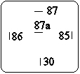
87 - 12V -> Relay to Air Lift 12V
87a - empty -> Don't Use
30 - 12V -> Battery to Relay
86 - Gnd -> Relay to Ground
85 - 12V -> Ignition-On Wire to Relay
With this set up, you won't be over taxing stock fuses (the Air Lift will be powered directly from the battery and have its own fuse) and you'll still have the functionality when the key is in the ON position.
Senior Member
Joined: Jun 2007
Posts: 361
Likes: 0
If you run their fused power line directly from the battery and through a relay, then use the wire that is hot with ignition as the switch, you'll have an isolated power circuit that is only active when the ignition is on.
87 - 12V -> Relay to Air Lift 12V
87a - empty -> Don't Use
30 - 12V -> Battery to Relay
86 - Gnd -> Relay to Ground
85 - 12V -> Ignition-On Wire to Relay
With this set up, you won't be over taxing stock fuses (the Air Lift will be powered directly from the battery and have its own fuse) and you'll still have the functionality when the key is in the ON position.
Trending Topics
Thread Starter
|
Junior Member
Joined: May 2007
Posts: 5
Likes: 0
From: Anaheim, CA
Thanks again for the replies. I assume then that this relay is something I will just pick up at my local auto parts store and wire up. Safe to say I have already found a wire that I can use for the "Ignition-On" wire 
Last edited by jimireb; Jul 6, 2009 at 03:49 PM. Reason: Add on...
Senior Member
Joined: Jun 2007
Posts: 361
Likes: 0
Just tell them you want a 12V relay. Not sure if there is an amp rating on them. Whatever your compressor motor amps are rated at or the fuse amperage is what you want. Tell them what you are doing they will know what you need for a relay.

Member
Joined: Sep 2008
Posts: 21
Likes: 0
Sorry to wake this from the dead, however I am wiring in an Air Lift compressor this weekend and will be running a relay as described in this post. My question is, per this schematic, where does the wire from the panel switch go? This looks like it allows the low pressure switch to automatically come on when the key is switched on. I need to know how to wire in the panel power wire to add air when additional pressure is needed.
I'm tracking how to do everything else.
Thanks in advance!
I'm tracking how to do everything else.
Thanks in advance!
Last edited by OC Dan; Nov 9, 2010 at 05:51 PM.

Technical Article Contributor
Joined: Jun 2002
Posts: 10,511
Likes: 10
From: Under the flightpath of old ORD 22R
No need to apologize for doing a search, and adding to the correct thread, that is why threads are kept and the search available 
Here is a generic relay diagram

In your case, you can use an add-a-fuse in the radio slot to trigger the relay coil. The added circuit only needs to be a 1A fuse, as it is only the coil load.
The connection to the battery from terminal #30 is fused for the load on the compressor and 87 goes to the compressor.
That is what I read for the description, not sure if I got it quite right ( is the relay for a low AMP circuit for the switch, and then there is another high AMP circuit ?? )
Here is a generic relay diagram
In your case, you can use an add-a-fuse in the radio slot to trigger the relay coil. The added circuit only needs to be a 1A fuse, as it is only the coil load.
The connection to the battery from terminal #30 is fused for the load on the compressor and 87 goes to the compressor.
That is what I read for the description, not sure if I got it quite right ( is the relay for a low AMP circuit for the switch, and then there is another high AMP circuit ?? )
Member
Joined: Sep 2008
Posts: 21
Likes: 0
If you run their fused power line directly from the battery and through a relay, then use the wire that is hot with ignition as the switch, you'll have an isolated power circuit that is only active when the ignition is on.
87 - 12V -> Relay to Air Lift 12V
87a - empty -> Don't Use
30 - 12V -> Battery to Relay
86 - Gnd -> Relay to Ground
85 - 12V -> Ignition-On Wire to Relay
With this set up, you won't be over taxing stock fuses (the Air Lift will be powered directly from the battery and have its own fuse) and you'll still have the functionality when the key is in the ON position.
87 - 12V -> Relay to Air Lift 12V
87a - empty -> Don't Use
30 - 12V -> Battery to Relay
86 - Gnd -> Relay to Ground
85 - 12V -> Ignition-On Wire to Relay
With this set up, you won't be over taxing stock fuses (the Air Lift will be powered directly from the battery and have its own fuse) and you'll still have the functionality when the key is in the ON position.
Last edited by OC Dan; Nov 10, 2010 at 10:58 PM.
Technical Article Contributor
Joined: Jun 2002
Posts: 10,511
Likes: 10
From: Under the flightpath of old ORD 22R
In the diagram above ( that I posted ) the add-a-fuse ( i.e. for the radio ) is run to the switch. The switch to terminal #85 on the relay.
This configuration the switch can only turn on the compressor when the radio can work ( accessory or run position on the key or until the door is opened for the delay ).
Make sure you install the add-a-fuse the correct direction, use a meter to find which side of the fuse is hot and which side is to the device. Pull the fuse and turn on the key, which ever side has power is to the ign source, the dead side is towards the radio.