
??Signal Processor??


Thread Starter
|
Member
Joined: Jul 2010
Posts: 54
Likes: 0
??Signal Processor??
Installing a new audio system, but want to keep my factory look.
Does anyone have experence installing a "signal processor". thinking of using the Kicker ZXSUM8. What exactly is "inputted" into the ZXSUM8? The manual shows "sub channel, Mid-sub channel, mid channel, and tweeter channel" as all seperate inputs. Don't have a wiring diagram. So can I just use any single signal as the input...say Front left speaker?
I don't have the premium sound package. (2010 FX4 Super Crew).
See this thread for details.
https://www.f150online.com/forums/200...rade-help.html
Thanks.
-Cesar

Senior Member
Joined: Oct 2010
Posts: 327
Likes: 1
From: Austin, Tx
I was in the same boat as you. I have a 2010 FX2 and wanting to keep the stock head unit while upgrading everything else. I looked at the ZSUM8, JL Cleansweep, and finally got a AudioControl LC6i.
I can not comment on the LC6i yet because I am installing everything this weekend.
There were a couple reasons I purchased the LC6i. One being, as I was visiting all the large car audio shops near where I live, they all said is was a really good unit. A couple of the shops recommended it didn't stock it and couldn't even order me one. The other main reason is I did many hours of online research and it seemed to be highly regarded by normal everyday people. Plus, as a side bonus I got it for a really good price and sometimes price does matter.
Good luck with your search.
Thread Starter
|
Member
Joined: Jul 2010
Posts: 54
Likes: 0
Langlowe,
I just realized the link above didn't work. So here it is again. Good luck with the install this weekend, let me know how it goes, and I might follow your lead. Thanks.
-Cesar
https://www.f150online.com/forums/20...rade-help.html
I just realized the link above didn't work. So here it is again. Good luck with the install this weekend, let me know how it goes, and I might follow your lead. Thanks.
-Cesar
https://www.f150online.com/forums/20...rade-help.html
Senior Member
Joined: Oct 2010
Posts: 327
Likes: 1
From: Austin, Tx
Installed everything this weekend. Man what a lot of work.
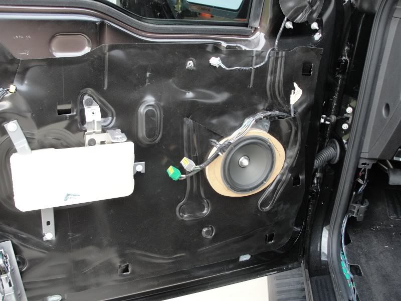
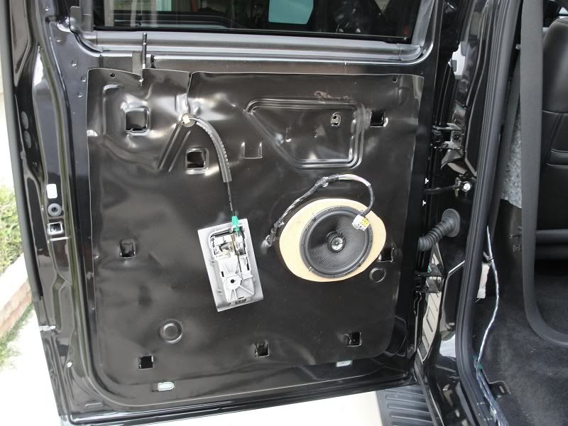
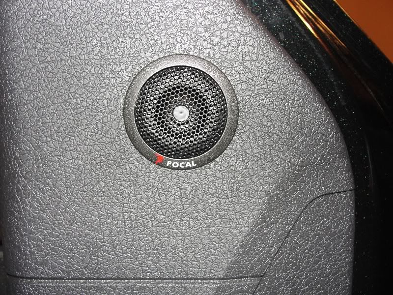
I put 6.5 components in the front doors and installed the tweaters up where the defroster vents are.
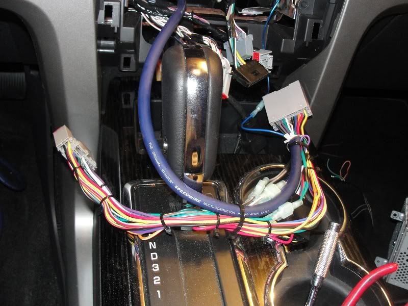
I used a Metra BT-5520 harness for the factory stereo and it worked like a charm. I pulled out the 4 extra wires that connected the two black BT connectors and the rest was plug and play. I cut the 8 speaker wires coming out of the Metra factory side and ran Speedwire 9 conductor to behind the rear seats.
I took the high level inputs and first hooked everything up without the LC6i and the Focal 165VR fronts and 165 CA1 rear fill sounded good but started lacking when the volume went up. I am running about 75rms to the front doors. My front 4 channel amp is on order so I used a loaner 2 channel with the same power rating.
I then hooked up the LC6i and what a diffence. I tuned the LC6i per the instructions which states to disconnect the rcas, turn the stereo up to 75%, turn the amp gains down and the LC6i gain up until the yellow clip light starts to flicker. The bass doesn't drop off and sounds ohh so much better. There is no hiss or alternator whine. It is clear and noise free.
With LC6i you take the front speakers high level leads and connect to channel 1. Rears to channel 2. Channel 3 i left open.
With our setup the LC6i you don't sum channel 2 with 1. That is only if you have a factory stereo that already has seperate mids and highs like the Sony option. Channel 3 is automatically bridged off channel 2 if no channel 3 input is present.
My sub and box are still on order so I haven't had a chance to test that out but I don't expect any problems.
I used the torx45 bolt holding the rear seatbelt mechanism, on the back wall, as my ground connection. I didn't want to mess with those rear seat bolts but I am about to cut the second one from the left down. They are absurdly tall and is kind of in the way of the amp rack.
I ran power and all right side speaker wire on the passenger channel. There is a gromment directly under the ECU in the engine bay that I feed my 4awg through. It came out right beside the glove box and down behind the interior fuse box. I ran the 9 conductor using the 9wire for remote amp turn on lead, it is internally shielded, along with all left side speaker wire down the drives side. The remote amp turn on lead is an add a fuse to location 41. You will need to "modify" the plastic sides on the fuse box to allow the lid to close. A couple snips with wire cutters did the trick for me. I have read you can tap into the blue wire in the passenger kick panel but I saw a lot of blue and at 2am didn't want to mess with it.
All told I spent over 25 hours and still have a little "house cleaning" but it was worth every minute.
Here is a complete list of the major parts I used for the install. I have a friend who is a master distributer with Kicker so I was getting those pieces for a lot less than retail.
Kicker ZX500.1 = Sub amp
Kicker ZX350.4 = Door amp
AudioControl LC6i = sound processor
Metra BT-5520 = factory wiring harness
Kicker ZXRC = Bass remote
Kicker ZI21 = RCA interconnects x3
Focal 165 VR = Front Components
Focal 165 CA 1 = Rear fills
Image Dynamics ID10D4
supercrew sub box
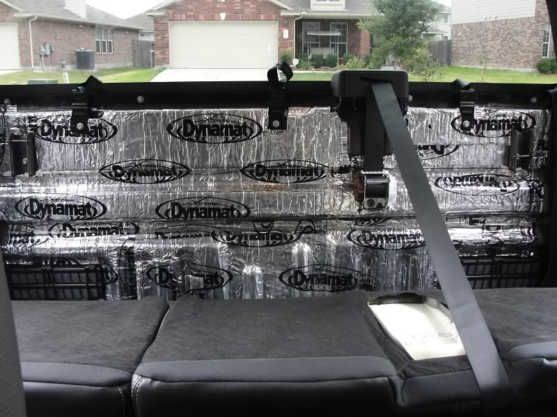
Dynamat Extreme Wedge packs 10425 x3 = rear wall
Dynamat Extreme Shop Pack 20410 = around door speakers
Stinger SHD20 = Ground Distribution Block
Stinger SHD820 = Power Distribution Block
Stinger SHD801 = Inline fuse block
Stinger 40amp MIDI fuse
Stinger 60amp MIDI fuse
Stinger 120amp MIDI fuse
Stinger 9 conductor speed wire = 20ft
Stinger Stinger SGW516BC 16ga= 2x 50ft
Stinger Stinger SHW510BC 10ga = 10ft
KnuKonceptz 4awg red = 18ft
KnuKonceptz 4awg black = 8ft
KnuKonceptz 8awg red = 3ft
KnuKonceptz 8awg black = 3ft
I put 6.5 components in the front doors and installed the tweaters up where the defroster vents are.
I used a Metra BT-5520 harness for the factory stereo and it worked like a charm. I pulled out the 4 extra wires that connected the two black BT connectors and the rest was plug and play. I cut the 8 speaker wires coming out of the Metra factory side and ran Speedwire 9 conductor to behind the rear seats.
I took the high level inputs and first hooked everything up without the LC6i and the Focal 165VR fronts and 165 CA1 rear fill sounded good but started lacking when the volume went up. I am running about 75rms to the front doors. My front 4 channel amp is on order so I used a loaner 2 channel with the same power rating.
I then hooked up the LC6i and what a diffence. I tuned the LC6i per the instructions which states to disconnect the rcas, turn the stereo up to 75%, turn the amp gains down and the LC6i gain up until the yellow clip light starts to flicker. The bass doesn't drop off and sounds ohh so much better. There is no hiss or alternator whine. It is clear and noise free.
With LC6i you take the front speakers high level leads and connect to channel 1. Rears to channel 2. Channel 3 i left open.
With our setup the LC6i you don't sum channel 2 with 1. That is only if you have a factory stereo that already has seperate mids and highs like the Sony option. Channel 3 is automatically bridged off channel 2 if no channel 3 input is present.
My sub and box are still on order so I haven't had a chance to test that out but I don't expect any problems.
I used the torx45 bolt holding the rear seatbelt mechanism, on the back wall, as my ground connection. I didn't want to mess with those rear seat bolts but I am about to cut the second one from the left down. They are absurdly tall and is kind of in the way of the amp rack.
I ran power and all right side speaker wire on the passenger channel. There is a gromment directly under the ECU in the engine bay that I feed my 4awg through. It came out right beside the glove box and down behind the interior fuse box. I ran the 9 conductor using the 9wire for remote amp turn on lead, it is internally shielded, along with all left side speaker wire down the drives side. The remote amp turn on lead is an add a fuse to location 41. You will need to "modify" the plastic sides on the fuse box to allow the lid to close. A couple snips with wire cutters did the trick for me. I have read you can tap into the blue wire in the passenger kick panel but I saw a lot of blue and at 2am didn't want to mess with it.
All told I spent over 25 hours and still have a little "house cleaning" but it was worth every minute.
Here is a complete list of the major parts I used for the install. I have a friend who is a master distributer with Kicker so I was getting those pieces for a lot less than retail.
Kicker ZX500.1 = Sub amp
Kicker ZX350.4 = Door amp
AudioControl LC6i = sound processor
Metra BT-5520 = factory wiring harness
Kicker ZXRC = Bass remote
Kicker ZI21 = RCA interconnects x3
Focal 165 VR = Front Components
Focal 165 CA 1 = Rear fills
Image Dynamics ID10D4
supercrew sub box
Dynamat Extreme Wedge packs 10425 x3 = rear wall
Dynamat Extreme Shop Pack 20410 = around door speakers
Stinger SHD20 = Ground Distribution Block
Stinger SHD820 = Power Distribution Block
Stinger SHD801 = Inline fuse block
Stinger 40amp MIDI fuse
Stinger 60amp MIDI fuse
Stinger 120amp MIDI fuse
Stinger 9 conductor speed wire = 20ft
Stinger Stinger SGW516BC 16ga= 2x 50ft
Stinger Stinger SHW510BC 10ga = 10ft
KnuKonceptz 4awg red = 18ft
KnuKonceptz 4awg black = 8ft
KnuKonceptz 8awg red = 3ft
KnuKonceptz 8awg black = 3ft
Last edited by Langlowe; Oct 25, 2010 at 05:00 PM.

Member
Joined: May 2010
Posts: 25
Likes: 0
From: Boise, Idaho
Sounds really similar to what I want to do here very soon. Have most of the parts, but waiting on a little more cash flow. Some pics would be awesome! If you can't get them up here mind sending me an e-mail?
Senior Member
Joined: Oct 2010
Posts: 327
Likes: 1
From: Austin, Tx
I didn't take pictures of every detail just a general overview of my work.
The amp rack is being covered this weekend or maybe next. You can see the long power and ground going to the small amp on the right. This is where the 4 channel will be mounted so I went ahead and made it ready to just be screwed in and the cables trimmed to fit.
The cables on the left still have to be routed behind the back felt. I had them down low and realized they needed to be higher in one of the channels for the rack to mount the way I wanted.
I am also going to move the location of the RCA routing from the LC6i. I will center it between the two crossovers.
You can't really tell because of the angle of the pics but everything is centered and spaced to within 1/32 of an inch.
One last thing. I read all kinds of discussion on the rear vents. Some say cover them, others say that causes more problems. I didn't cover them with dynamat but what I did do was follow the advice of some small thread I read. I took a 59 cent household AC filter and cut enough to cover and doubled it up. I then used AC foil tape and put in on top of each vent. They still work but are nowhere near as loud as they were. My AC on full blast works great wth no whistles.
Trending Topics

Member
Joined: Jun 2010
Posts: 82
Likes: 0
From: West Deptford, NJ
Very nice write up. I am going to be installing my amp this weekend for my door speakers. Did you run speed wire 9 from the head unit to the LC6i and then run speed wire 9 from the amps back up to the exisiting ford speaker wire behind the head unit?
Senior Member
Joined: Oct 2010
Posts: 327
Likes: 1
From: Austin, Tx
However, when I checked the door boots I was lucky in that they did not have the molex connectors. At that point I changed my mind, even though at only 75rms the factory wire should have been fine.
Don't get me wrong, it was a pita to get that 16 gauge sheathed cable through them boots. What I found was that fishing a nylon cord through the boot and then using a sinch knot around the speaker cable along with a shot is wd40 made it a little easier.
Also, I fished through the boots first and them into the doors and cab. Trying to go through everthing in one shot would be almost impossible.
Senior Member
Joined: Oct 2010
Posts: 327
Likes: 1
From: Austin, Tx
Sorry about this cocarva.
I didn't mean to thread jack.
I started a new thread for myself.
https://www.f150online.com/forums/sp...g-writeup.html
I didn't mean to thread jack.
I started a new thread for myself.
https://www.f150online.com/forums/sp...g-writeup.html

Senior Member
Joined: Oct 2002
Posts: 239
Likes: 0
I have the same fuse for power at battery. Check and make sure fuse is tight to block. Mine was loose and wondering why I was losing power. What did you do for remote turn on wire? I'm using a mtx req5 sig processer, using auto sensing right now. Its terrible I need to get remote hooked up.
Senior Member
Joined: Oct 2010
Posts: 327
Likes: 1
From: Austin, Tx
I have the same fuse for power at battery. Check and make sure fuse is tight to block. Mine was loose and wondering why I was losing power. What did you do for remote turn on wire? I'm using a mtx req5 sig processer, using auto sensing right now. Its terrible I need to get remote hooked up.
With high level leads like that a low amp turn on lead should have on effect.