

Auxiliary reverse lights.. Not the typical questions


Thread Starter
|
Senior Member
Joined: Dec 2012
Posts: 148
Likes: 0
Auxiliary reverse lights.. Not the typical questions
Ok so I live in the middle of the woods and often reverse up my drive at night. The factory reverse lights do nothing for me , especially since I have 2.5% tint on the back windows. So, couple quick questions... One, if someone could verify that the purple wire going into my 7 pin is in fact the trailer reverse light wire. 2, if I simply splice that line into the hot wire on the lights then the lights will come on while in reverse. 3, the black wire on the 7 pin is a constant hot wire as well, so if I run a switch can i just tie into that wire for the switch? I may or may not run a switch to control turning them on on demand. The only reason I would want to be able to do that is to flash them at people who ride my ***. Since, this is slightly dangerous and like using pepper spray (which I wont buy) I know I would be using it all the time. Anyways all help is appreciated. I did do a search on this and only came across info on 04+ or some very confussing diagrams. I am not an electrical expert and dont really want to run all kinds of new wires and relays and diodes and switches.
On my 98, purple is indeed the reverse light. But you need to put a relay back there for the lights and run a fused 6 or 8 gauge to the battery if you want maximum output.
Also, flashing reverse lights at someone who is riding your butt is only going to exacerbate the situation. Just pull over and let them pass.
Also, flashing reverse lights at someone who is riding your butt is only going to exacerbate the situation. Just pull over and let them pass.
Thread Starter
|
Senior Member
Joined: Dec 2012
Posts: 148
Likes: 0
Thanks for the info buddy. I dont really need to light up a neighborhood just trying to shine a little more light on the driveway. Im thinking some led 4" fog lights should do the trick and be a minimal draw on power. Somewhere around one amp. That wire is good up to 8 amps so I think I should be fine. I know that flashing the lights at people would probably make things worse, and I also know that I would do it too. So probably wont put a switch in just to keep the temptation down. Again thanks for the info buddy.

Technical Article Contributor
Joined: Mar 2012
Posts: 154
Likes: 0
Please use a relay and a good strand of 10-12ga wire depending on wattage.
This can give you some options
I know there are a few write ups on how to wire up a relay using an aux switch, however, I wanted to do a write up on using 3 different means of turn on leads ( 1. Switch in the cab, 2. Switch on the tow harness bracket, 3. using reverse as a lead). There are different ways to doing this, but this one fit my needs the best.
First: Realize there are lots of different configurations for this, I will try to name a few of the most popular setups before I get into the "how to" part. Choose which configuration fits your needs. * I won't name all of them* but you should be able to figure this out once you read the entire post. If you get confused, back track yourself and review how each relay works separately. Here are some of the basics and additional info:
http://www.f150forum.com/f75/auxilar...cluded-148074/
Keeping every switch on a separate circuit (RECOMMENDED)
If you want to keep everything switch from effecting and turning off the other, you will need 3 relays (my way to keep power efficient). By keeping the switches and circuits separate you won't have to worry about turning your inside switch on and your factory reverse lights coming on. Another scenario which could occur if you dont keep them separate is: you could leave your inside switch off(in the cab) and your switch on the tow harness bracket will not work, so your lights will not work via the outside switch.
Keeping Reverse separate, but allowing your rear switch to have priority over the cab switch. *This is the way I decided to go.* If I want to go behind my truck with the truck not on and flip my lights on, they will work independently. I like this circuit since I do alot of camping and unloading at night. Note: The switch on the rear will have the full amperage of the lights going to it, so make sure to get a 30amp external switch. The switch in the cab will only serve as a remote turn on lead for the first relay.
There are way too many configurations to name, but another one that could be beneficial is adding an aux switch to be able to turn off your back up lights when in reverse. I wont go into detail on this one, as I chose to not go this route. However, here is another option to show you similarities and differences.
The route I chose and will be showing you how to:
Keeping Reverse separate, but allowing your rear switch to have priority over the cab switch.
For my setup, I will be using two 30-amp heavy duty relays. The relays I chose are 5pin and have two power outlets(pins 87, 87a). Some relays can be used outside, check with your parts store and make sure they are waterproof before installing anything on the exterior of your truck. If you can't find any waterproof relays, you can always hook them up in the cab and run wires to the sources(takes more wire obviously). Or waterproof them with plasti-dip as another member has already suggested.
Depending on your lights wattage, your relays amperage may vary.... See this post for more info on wattage/amps/volts. Your wiring needs to be of appropriate gauge as well. For almost all off-road lights/fog lights 14 gauge wire will be sufficient. (conditional on how far they are from your battery source).
Materials:
1) One set of back up lights (fog lights)
2) 1 12V- 30amp exterior aux switch
3) 1 12V- Interior switch
4) Three 30-Amp Exterior Relays (5 pin) and one-5-10amp fuse
5) Three 30-amp fuse's and holders and one 5-10amp fuse holder.
6) Depending on your configuration and relay positioning.. around 50-75 feet of 14 gauge wire. *I bought 3 different colors of wire for this how to, it makes wiring much easier to keep up with.
Red- All 12V fused power (to relays) and turn on leads
Yellow - Power to Lamps
Black - Ground
7) 16 - 1/4" female connectors.
8) 2- Self taping screws if you are doing the exterior mounted relays.
Tools:
1) Wire Cutters/Need Nose plier
2) Soldering iron
3) Electrical Tape
4) Drill (for self taping screws), mounting lights, and mounting exterior aux. switch.
Positioning hardware(Lights, Relays, Switches)
First: Position your lights where you would like them on the back of the truck. I actually tack welded mine to the steel towing bar. I wanted to position them so I could fold them upwards and be out of sight from people, and also keep the lens from getting damaged driving.
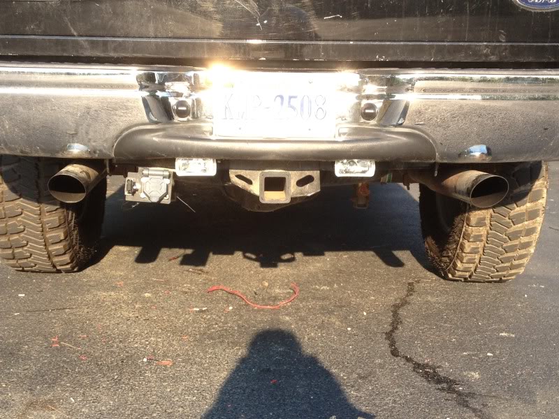
Second: Mount your External 30-amp Switch on the tow harness bracket.
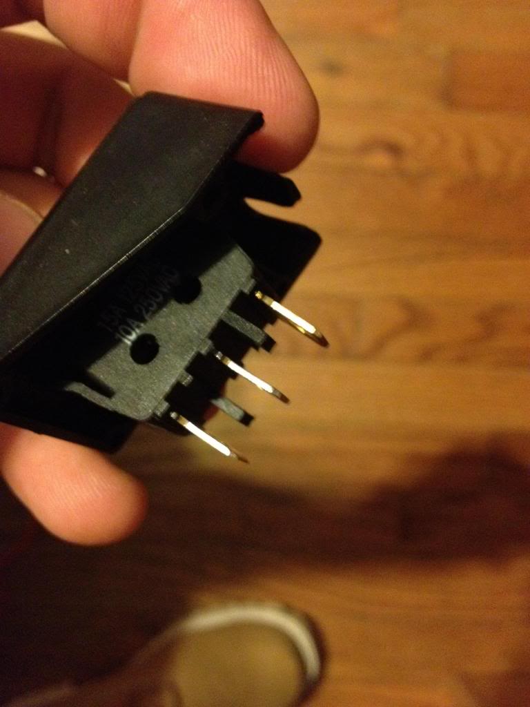
Third: Mount your interior switch whenever you would like. (Leave access, we will need to get to this in a moment). Should look like this with 2 or 3 pins.
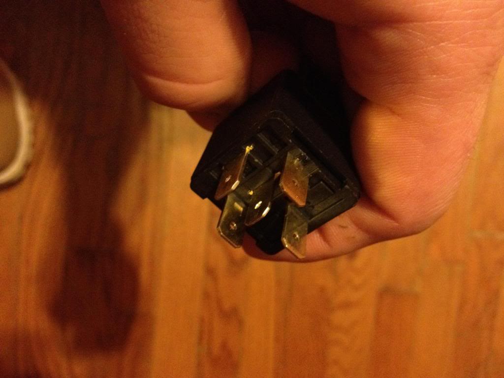
Fourth: Mount your two relays whenever you would like(closer to the lights, the easier the wiring).
Each should look like this.
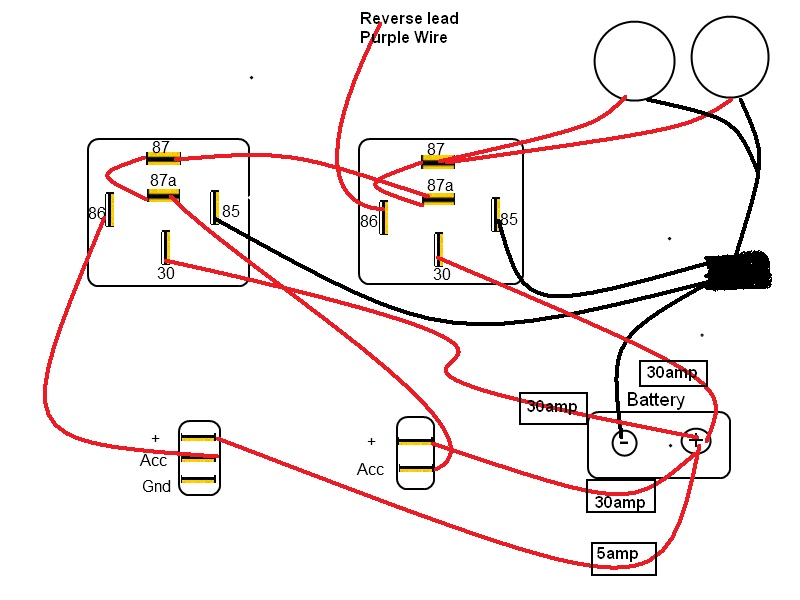
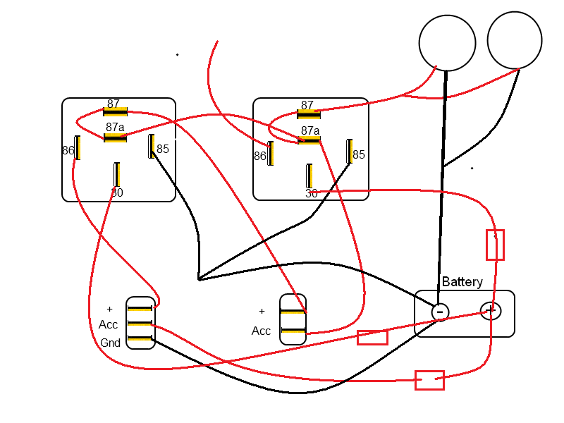
Before running wires, here is a review on what wires go where.
-a standard bosch-style relay will have 4 or 5 numbered leads (30, 85, 86, 87, and sometimes 87a). why they picked those numbers, I have no clue; but I can tell what they hook up to.
-30 = constant [positive (+)] power (usually wired directly to car battery)
-85 = coil ground (wired to the negative (-) battery terminal or any grounded metal panel in the car)
-86 = coil power (wired to the control source. could be a switch, or it could be the car's IGN or ACC circuit.)
-87 = switched [positive (+)] power output. (when the relay coil is powered, lead/pin 87 is connected to lead/pin 30)
-87a = [on 5 lead/pin relays only] this lead/pin is connected to lead/pin 30 when the coil is NOT powered.
Finally: Time to run the wires, and figure out how this configuration works.
*DISCONNECT THE GROUND ON YOUR BATTERY BEFORE PROCEEDING*
For the following steps I will relate and reference the picture below.
Note: Realy #1 is on left, Realy #2 is on right.
This particular part will relate to all "FUSED" wires from the battery (4), and all wires running to and from the aux switches.
1) Run two separate 14ga "30 amp fused" wires from the battery to the #30 pin on each relay.
2) Next we will run another 14ga. "30 amp FUSED" wire from the battery to the #ACC point on the external aux. switch(Once of the tow harness).
Once that is done, on the same external aux. switch run another strand of 14ga. wire from the + on the switch to #87a or#87 on the first relay.
3) Now run a strand of 14-16ga wire from the battery "5amp FUSED" to the #acc pin on the internal aux switch(one in the cab). Then, on the same internal switch run another strand of 14ga. wire from the + on the switch to pin #86 on relay number 1.
*If your interior switch has an light (an extra pin/ ground) then run a wire from the pin labeled ground to any ground in the cab of your truck. We are now done wiring in switches and fuses.
Wiring all the pins on the relay to the lights and other locations:
Concentration on relay #1:
We should already have pin #30, 87a, and #86 wired in.
1) Now run another piece of "Black" (doesn't matter what color) 14ga wire from pin #85 to a solid ground
2) *****Note: Pin #87 and #87a will have two wires attached each, so dont crimp until done.
The only pin left untouched on relay #1 is pin #87 (both 87 and 87a conduce power) . These pins are the output of the relay (up to 30amps).
So run another piece of 14ga wire from pin #87 on relay #1 to, pin #87a on relay # 2.
3) Run a very short strand from (87 to 87a) to help the relay's efficiency.
*relay #1 is now finished*
Concentration on Relay #2
The only pin on relay#2 covered right now should be, pin #30 and #87a.
1) Run 14ga. wire from pin #85 to a solid ground.
2) Now we need to get into our trailer harness and find the purple wire. We will tap into that wire and run a short strand of 14ga. wire to pin #86 on relay #2.
3) *****Note: Pin #87 and #87a will have two wires attached each, so dont crimp until done.
Run a short strand of 14ga from pin #87 to #87a (pin #87a should already have a wire running from pin #87 on relay #1).
Now fore the wires on the lights
Finally, wire both positive leads of the lights to pin #87 on relay #2.
That completes all the relay wiring. Now ground the lights to an appropriate location. Both lights need to be grounded. (doesn't all have to be the same spot).
Now, replace the (-) terminal on the battery and try out your work.
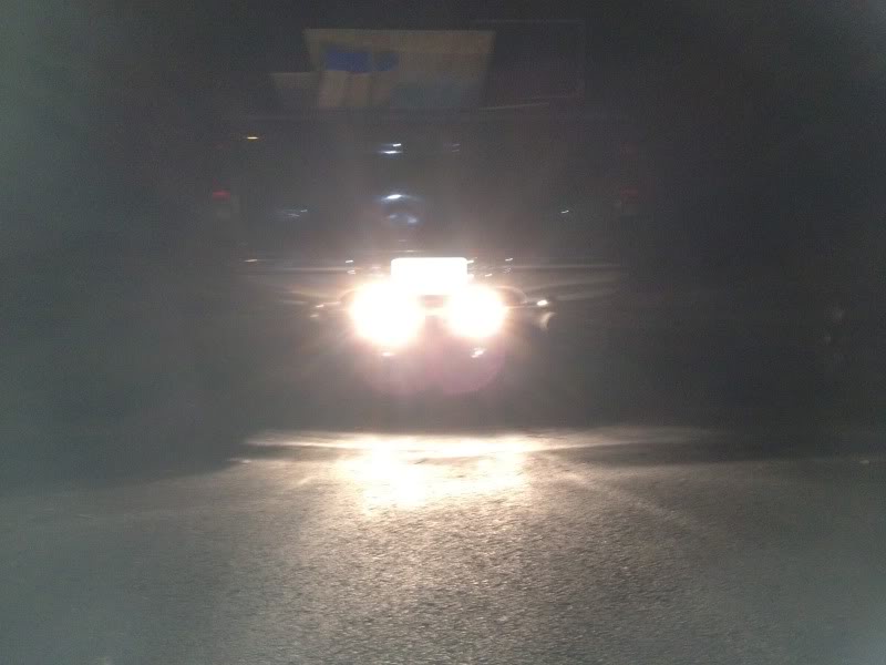
Turned on without reverse.
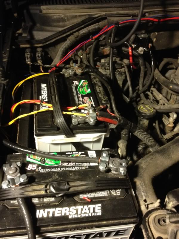
I hid my fuses to side of the battery.
This can give you some options
I know there are a few write ups on how to wire up a relay using an aux switch, however, I wanted to do a write up on using 3 different means of turn on leads ( 1. Switch in the cab, 2. Switch on the tow harness bracket, 3. using reverse as a lead). There are different ways to doing this, but this one fit my needs the best.
First: Realize there are lots of different configurations for this, I will try to name a few of the most popular setups before I get into the "how to" part. Choose which configuration fits your needs. * I won't name all of them* but you should be able to figure this out once you read the entire post. If you get confused, back track yourself and review how each relay works separately. Here are some of the basics and additional info:
http://www.f150forum.com/f75/auxilar...cluded-148074/
Keeping every switch on a separate circuit (RECOMMENDED)
If you want to keep everything switch from effecting and turning off the other, you will need 3 relays (my way to keep power efficient). By keeping the switches and circuits separate you won't have to worry about turning your inside switch on and your factory reverse lights coming on. Another scenario which could occur if you dont keep them separate is: you could leave your inside switch off(in the cab) and your switch on the tow harness bracket will not work, so your lights will not work via the outside switch.
Keeping Reverse separate, but allowing your rear switch to have priority over the cab switch. *This is the way I decided to go.* If I want to go behind my truck with the truck not on and flip my lights on, they will work independently. I like this circuit since I do alot of camping and unloading at night. Note: The switch on the rear will have the full amperage of the lights going to it, so make sure to get a 30amp external switch. The switch in the cab will only serve as a remote turn on lead for the first relay.
There are way too many configurations to name, but another one that could be beneficial is adding an aux switch to be able to turn off your back up lights when in reverse. I wont go into detail on this one, as I chose to not go this route. However, here is another option to show you similarities and differences.
The route I chose and will be showing you how to:
Keeping Reverse separate, but allowing your rear switch to have priority over the cab switch.
For my setup, I will be using two 30-amp heavy duty relays. The relays I chose are 5pin and have two power outlets(pins 87, 87a). Some relays can be used outside, check with your parts store and make sure they are waterproof before installing anything on the exterior of your truck. If you can't find any waterproof relays, you can always hook them up in the cab and run wires to the sources(takes more wire obviously). Or waterproof them with plasti-dip as another member has already suggested.
Depending on your lights wattage, your relays amperage may vary.... See this post for more info on wattage/amps/volts. Your wiring needs to be of appropriate gauge as well. For almost all off-road lights/fog lights 14 gauge wire will be sufficient. (conditional on how far they are from your battery source).
Materials:
1) One set of back up lights (fog lights)
2) 1 12V- 30amp exterior aux switch
3) 1 12V- Interior switch
4) Three 30-Amp Exterior Relays (5 pin) and one-5-10amp fuse
5) Three 30-amp fuse's and holders and one 5-10amp fuse holder.
6) Depending on your configuration and relay positioning.. around 50-75 feet of 14 gauge wire. *I bought 3 different colors of wire for this how to, it makes wiring much easier to keep up with.
Red- All 12V fused power (to relays) and turn on leads
Yellow - Power to Lamps
Black - Ground
7) 16 - 1/4" female connectors.
8) 2- Self taping screws if you are doing the exterior mounted relays.
Tools:
1) Wire Cutters/Need Nose plier
2) Soldering iron
3) Electrical Tape
4) Drill (for self taping screws), mounting lights, and mounting exterior aux. switch.
Positioning hardware(Lights, Relays, Switches)
First: Position your lights where you would like them on the back of the truck. I actually tack welded mine to the steel towing bar. I wanted to position them so I could fold them upwards and be out of sight from people, and also keep the lens from getting damaged driving.
Second: Mount your External 30-amp Switch on the tow harness bracket.
Third: Mount your interior switch whenever you would like. (Leave access, we will need to get to this in a moment). Should look like this with 2 or 3 pins.
Fourth: Mount your two relays whenever you would like(closer to the lights, the easier the wiring).
Each should look like this.
Before running wires, here is a review on what wires go where.
-a standard bosch-style relay will have 4 or 5 numbered leads (30, 85, 86, 87, and sometimes 87a). why they picked those numbers, I have no clue; but I can tell what they hook up to.
-30 = constant [positive (+)] power (usually wired directly to car battery)
-85 = coil ground (wired to the negative (-) battery terminal or any grounded metal panel in the car)
-86 = coil power (wired to the control source. could be a switch, or it could be the car's IGN or ACC circuit.)
-87 = switched [positive (+)] power output. (when the relay coil is powered, lead/pin 87 is connected to lead/pin 30)
-87a = [on 5 lead/pin relays only] this lead/pin is connected to lead/pin 30 when the coil is NOT powered.
Finally: Time to run the wires, and figure out how this configuration works.
*DISCONNECT THE GROUND ON YOUR BATTERY BEFORE PROCEEDING*
For the following steps I will relate and reference the picture below.
Note: Realy #1 is on left, Realy #2 is on right.
This particular part will relate to all "FUSED" wires from the battery (4), and all wires running to and from the aux switches.
1) Run two separate 14ga "30 amp fused" wires from the battery to the #30 pin on each relay.
2) Next we will run another 14ga. "30 amp FUSED" wire from the battery to the #ACC point on the external aux. switch(Once of the tow harness).
Once that is done, on the same external aux. switch run another strand of 14ga. wire from the + on the switch to #87a or#87 on the first relay.
3) Now run a strand of 14-16ga wire from the battery "5amp FUSED" to the #acc pin on the internal aux switch(one in the cab). Then, on the same internal switch run another strand of 14ga. wire from the + on the switch to pin #86 on relay number 1.
*If your interior switch has an light (an extra pin/ ground) then run a wire from the pin labeled ground to any ground in the cab of your truck. We are now done wiring in switches and fuses.
Wiring all the pins on the relay to the lights and other locations:
Concentration on relay #1:
We should already have pin #30, 87a, and #86 wired in.
1) Now run another piece of "Black" (doesn't matter what color) 14ga wire from pin #85 to a solid ground
2) *****Note: Pin #87 and #87a will have two wires attached each, so dont crimp until done.
The only pin left untouched on relay #1 is pin #87 (both 87 and 87a conduce power) . These pins are the output of the relay (up to 30amps).
So run another piece of 14ga wire from pin #87 on relay #1 to, pin #87a on relay # 2.
3) Run a very short strand from (87 to 87a) to help the relay's efficiency.
*relay #1 is now finished*
Concentration on Relay #2
The only pin on relay#2 covered right now should be, pin #30 and #87a.
1) Run 14ga. wire from pin #85 to a solid ground.
2) Now we need to get into our trailer harness and find the purple wire. We will tap into that wire and run a short strand of 14ga. wire to pin #86 on relay #2.
3) *****Note: Pin #87 and #87a will have two wires attached each, so dont crimp until done.
Run a short strand of 14ga from pin #87 to #87a (pin #87a should already have a wire running from pin #87 on relay #1).
Now fore the wires on the lights
Finally, wire both positive leads of the lights to pin #87 on relay #2.
That completes all the relay wiring. Now ground the lights to an appropriate location. Both lights need to be grounded. (doesn't all have to be the same spot).
Now, replace the (-) terminal on the battery and try out your work.
Turned on without reverse.
I hid my fuses to side of the battery.

Senior Member
Joined: Jul 2004
Posts: 6,200
Likes: 39
From: Easton, Pa.
All you need is a single relay that operates off the normal reverse light circuit to ground, to cut through power from a new power lead fused at the battery.
Point the lights at a bit of an angle each side.
With window tinting you need lights with some power otherwise it's like trying to see through a welding helmet or you roll the driver side window down and use the side mirror..
Good luck.
Point the lights at a bit of an angle each side.
With window tinting you need lights with some power otherwise it's like trying to see through a welding helmet or you roll the driver side window down and use the side mirror..
Good luck.
Technical Article Contributor
Joined: Mar 2012
Posts: 154
Likes: 0
All you need is a single relay that operates off the normal reverse light circuit to ground, to cut through power from a new power lead fused at the battery.
Point the lights at a bit of an angle each side.
With window tinting you need lights with some power otherwise it's like trying to see through a welding helmet or you roll the driver side window down and use the side mirror..
Good luck.
Point the lights at a bit of an angle each side.
With window tinting you need lights with some power otherwise it's like trying to see through a welding helmet or you roll the driver side window down and use the side mirror..
Good luck.
1) Turns on in reverse
2) Switch in the cab to turn on or off
3) Switch on the towing bracket in case we are camping or loading a trailer
Trending Topics

Technical Article Contributor
Joined: Oct 2005
Posts: 25,641
Likes: 19
From: MI
ibd , -Great write-up.
Tomzilla83
This might be more than you want to know, anyway, -
No, don't solder to the relay. Use the proper connectors for the relay. You solder the wires together and the connectors onto the wire, then use the correct size adhesive type heat shrink tubing (weather proof). I'm not sure if this was mentioned, but you can also use plastic dip in the pint or quart can to weather seal.
Knowing how to wire it up is just one process. You also want the best weather proof connections; -back there anyway.
The best Soldering Irons are made by Weller (anything blue lol). Night and day diff.
Best solder for what your doing, = Kester, rosin core "44" .80mm (.031")
Corrosion resistant or adhesive Heat shrink tubing. Here's some
Thread Starter
|
Senior Member
Joined: Dec 2012
Posts: 148
Likes: 0
Thanks for the info JBrew. The thing is I know nothing about sodering other than it is similar to welding on a much smaller scale. I dont have a sodering gun or access to one and cant justify buying one for a single project. Is there a way to do this without sodering anything ?

Senior Member
Joined: Mar 2013
Posts: 170
Likes: 0
Thanks for the info JBrew. The thing is I know nothing about sodering other than it is similar to welding on a much smaller scale. I dont have a sodering gun or access to one and cant justify buying one for a single project. Is there a way to do this without sodering anything ?
EDIT: I should add it's pretty foolproof in this kind of wiring too, and easy to learn
 Don't cheap out on tools
  Or find a buddy with one to give you a hand if you can.
Last edited by far-trader; May 6, 2013 at 12:07 AM.
Senior Member
Joined: Mar 2013
Posts: 170
Likes: 0
Technical Article Contributor
Joined: Oct 2005
Posts: 25,641
Likes: 19
From: MI
Yea learning how to solder, sweat plumbing or whatever is the easiest thing in the world. The only thing you better know is keep that tip tinned or you can smoke it lol. That can be taught easily. I use a 2 Weller's, -depending upon what I'm doing, - Fixing PCB's or just joining wire (the easiest to learn). Can't really compare it to welding , - because that's not a fair comparison lol. It took me quite a bit of time to weld worth a snot. Soldering was easy.
Get a cheap one Iron, you don't need much for joining that wire. Keep the tip good and tinned. Tin it right before you shut it off every time. You have to keep the tip close to perfect or that cheap one won't work that well for long. Everything can be taught easily, you just have to be interested lol.
Get a cheap one Iron, you don't need much for joining that wire. Keep the tip good and tinned. Tin it right before you shut it off every time. You have to keep the tip close to perfect or that cheap one won't work that well for long. Everything can be taught easily, you just have to be interested lol.
Last edited by jbrew; May 7, 2013 at 02:50 AM. Reason: Moe BS'en

Junior Member
Joined: Sep 2013
Posts: 1
Likes: 0
I installed a second set of backup lights, tied them into backup wires already on the truck and used the screw hole that holds the bumper to the frame-install works great there. The only problem I'm having is they only work when the ignition is ON, the engine is OFF and I put the truck in reverse. When the truck is running and I put it into reverse they turn on briefly and then shut off, therefore rendering them useless. It's not the fuse...not sure about a computer override mechanism...

