Wiring problem of manufactured flush mounted bolt LED lighting unit
#1
 01-17-2018, 04:04 AM


Join Date: Jan 2018
Posts: 1
Likes: 0
Received 0 Likes
on
0 Posts
Wiring problem of manufactured flush mounted bolt LED lighting unit
In my search to find the best way to complete this pet project on my truck, I found this site. I've searched but as I am using a manufactured flush mounted bolt LED lighting unit I still have some questions on how best to set-up the wiring to get the LEDs to do what I want.
Background: I found this Bolt LED when looking through a car forum the other day - http://www.oznium.com/led-bolt/tech I've been trying to find something low-profile that has a simple and secure mechanism to hold it in place. Based on the reviews, these LEDs seem to be pretty decent quality. What I want to do is set-up 4 on each side of my truck along the toe plate of each running board and have them act as both additional parking lights and turn signals. I had previously installed LED light bars and wired them up to my parking lamp and turn signal sources and ground for each side of the car.
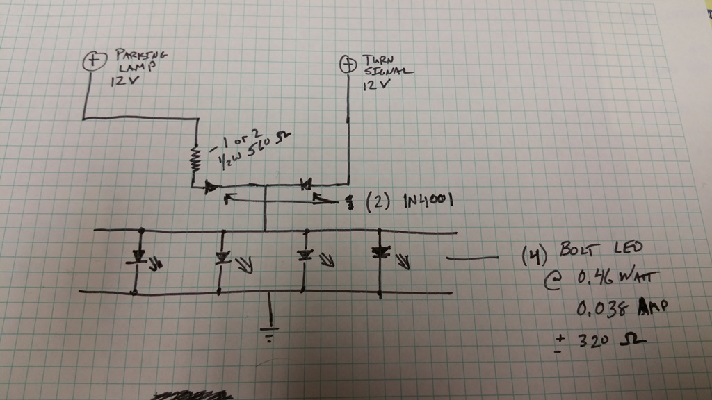
I've attached how I think the wiring should be done. I want to make sure I won't be harming the Bolt LEDs. I saw one post talking about the 2 currents "adding together" when both the parking light and turn signal are on. Do I need to be concerned with frying anything? Will the 1N4001 Diode(datasheet: http://www.kynix.com/uploadfiles/pdf86758/1N4001.pdf)be sufficient for this application? Should I assume a higher voltage than 12V? Is wiring the Bolts in parallel the best method or would wiring them in series make more sense?

Thanks for any help you can provide!
Background: I found this Bolt LED when looking through a car forum the other day - http://www.oznium.com/led-bolt/tech I've been trying to find something low-profile that has a simple and secure mechanism to hold it in place. Based on the reviews, these LEDs seem to be pretty decent quality. What I want to do is set-up 4 on each side of my truck along the toe plate of each running board and have them act as both additional parking lights and turn signals. I had previously installed LED light bars and wired them up to my parking lamp and turn signal sources and ground for each side of the car.
I've attached how I think the wiring should be done. I want to make sure I won't be harming the Bolt LEDs. I saw one post talking about the 2 currents "adding together" when both the parking light and turn signal are on. Do I need to be concerned with frying anything? Will the 1N4001 Diode(datasheet: http://www.kynix.com/uploadfiles/pdf86758/1N4001.pdf)be sufficient for this application? Should I assume a higher voltage than 12V? Is wiring the Bolts in parallel the best method or would wiring them in series make more sense?
Thanks for any help you can provide!
#2
01-19-2018, 09:01 PM

Junior Member
Join Date: Sep 2017
Location: Volcano, CA
Posts: 7
Likes: 0
Received 0 Likes
on
0 Posts
Okay so a couple things:
1) The turn signal path has no resistor in it. This probably isnt what you want (the turn signals would be WAY brighter than the parking lights) but maybe you want that. (You could diode-OR the two sources together and use ONE resistor though, however in that case, the resistor needs to be in the circuit after the two diodes not on the leg that leads to the diode on the Parking lamp leg. (ie. put it in that vertical segment after the the two diodes and before the 4 ones (which are the actual lights). BTW be sure to use a diode rated for the full value of the current to all the LEDs (which would be at least 120 milliamps in this case) The 1N4001 has a 1.0 amp rating for continuous use so its ok for this task (and they're cheap).
2) I found some question that says the LED contains a 470 ohm resistor. At 13.6Volts (which is nominal car voltage although its called "12 Volts" for historical reasons, when the engine is running its 13.6 or so) a 470 ohm resistor will produce a current of 13.6/470 = 29 milliamps (which is obviously the "bright" setting).
So lets put 4 of those in parallel - that gives you 120 milliamps for 4 LEDs with no resistor. with 560 ohms in series, you'll get 14 milliamps each or 56ma for 4. If you want to put an "upstream" resistor to dim them a bit, and use a 560 ohm resistor as suggested, that resistor needs to be: I**2 * R = 0.056 * 0.056 * 560 = 1.75 watt (I'd use a 3-5W resistor, just to be safe) The current *adds* and the power into the resistor goes up as the SQUARE of the current. (which is why a 1/2 watt resistor works for 1 LED but you need an 2+ watt one for 4). If you use a 1/2 watt one, it will very quickly heat up and catch fire...
So you can do the same thing by using an individual 1/2 watt 560 ohm resistor *on each leg* next to the individual LED btw. I probably would go for the single larger resistor but its your preference.
Using no resistor will produce 29 milliamps through the LED at 13.6 volts (bright)
Using a single 560 ohm resistor will lower the current through the LED to 14 milliamps. (less bright)
Using 2 560 ohm resistor in series will lower the current to 8.5milliamps. (dimmer)
You can get dimmer by using more resistors in series but you probably wont wont to except in a panel mount situation. Since 1/2 watt resistors are cheap if you do with an LED next to each resistor in series, i'd say get a couple of different values (560, maybe 1K) and see what you like. Try it at night because it may be offensively bright at night but ok in the day.
Last edited by n3ckf; 01-19-2018 at 09:23 PM.
#4
08-25-2018, 07:37 PM


#5
08-26-2018, 01:22 AM
I'm not an expert. I've never drawn a lighting diagram like that. But I have wired up a lot of aftermarket lighting.
In the past, with high wattage halogen lamps, the biggest concern was the amp draw, overheating, and risk of electrical fires.
With modern LED having such a low amp draw, the level of difficulty has gone down. Almost every LED light bar I've installed in the last few years, I have used a 5 or 10 amp fuse, with a SPST relay. I don't think I've seen any light bar bench test over 10 amp, with most of them being 5 amp or less. Sometimes the coil is switched with a toggle, sometimes connected to the high beam wire so that no wiring has to go through the firewall. Some of the LED spot lamps and flood lamps have such a low amp draw, 3 amp or less, that you can run it through a toggle switch with a fuse. There are now remote control switched LED light bar drivers which also connect fused, directly to the battery, so that all wiring is under the hood and you don't have to run wires through the firewall and drill the dash for a switch. One brand of light bar only has a remote control, with the driver built into the light bar, and you only have to run a fused connection to the battery.
#6
02-08-2021, 11:37 AM