
Windows and high draw problem


Thread Starter
|
Technical Article Contributor
Joined: Feb 2008
Posts: 8,673
Likes: 0
From: Rosenberg/Baytown TX
Windows and high draw problem
So I got an aftermarket power window kit for my truck and it cam with all the wiring done up. I hooked it to the battery to test it and it runs great. I'm going to integrate the kit into the factory switches I have and got both the aftermarket and factory wiring diagrams. Picked my wires and tapped them into the after market wiring. This way I have two switches to test and make sure it all works.
So now I hook the harness up to the battery again and then the factory switches get power. I start with the passenger switch and the passenger aftermarket switch and the factory one have the motor running really week. And drawing huge amount of current. The driver side passenger switch runs the same motor just fine.
So I run a relay to power the factory switches and it's still drawing huge snouts of power and has the motor running very week. Also blows the fuse and same thing using the factory driver side passenger switch.
So my question is how do the factory switches with just short amouts of wirig coming off them draw so much power. Why does the relay not help or how should it be wired. How come tapping into the working wiring from the aftermarket kit cause the system to draw huge amounts of power.
Looking for any advice to fix this before I install the kit

Technical Article Contributor
Joined: Jun 2002
Posts: 10,511
Likes: 10
From: Under the flightpath of old ORD 22R
Do you have a URL to the install directions or can you scan them and post them here ?
Hoping for a diagram for the aftermartket kit, not just the plug A into connector B type directions
Hoping for a diagram for the aftermartket kit, not just the plug A into connector B type directions
Thread Starter
|
Technical Article Contributor
Joined: Feb 2008
Posts: 8,673
Likes: 0
From: Rosenberg/Baytown TX
heres what ive got.
this is the link for the install directions
http://www.pacificautotronics.com/TX...nstallinst.pdf
this is the diagram they emailed me
ive just tapped my factory switch leads into the wiring show thats it.
this is the link for the install directions
http://www.pacificautotronics.com/TX...nstallinst.pdf
this is the diagram they emailed me
ive just tapped my factory switch leads into the wiring show thats it.
Technical Article Contributor
Joined: Jun 2002
Posts: 10,511
Likes: 10
From: Under the flightpath of old ORD 22R
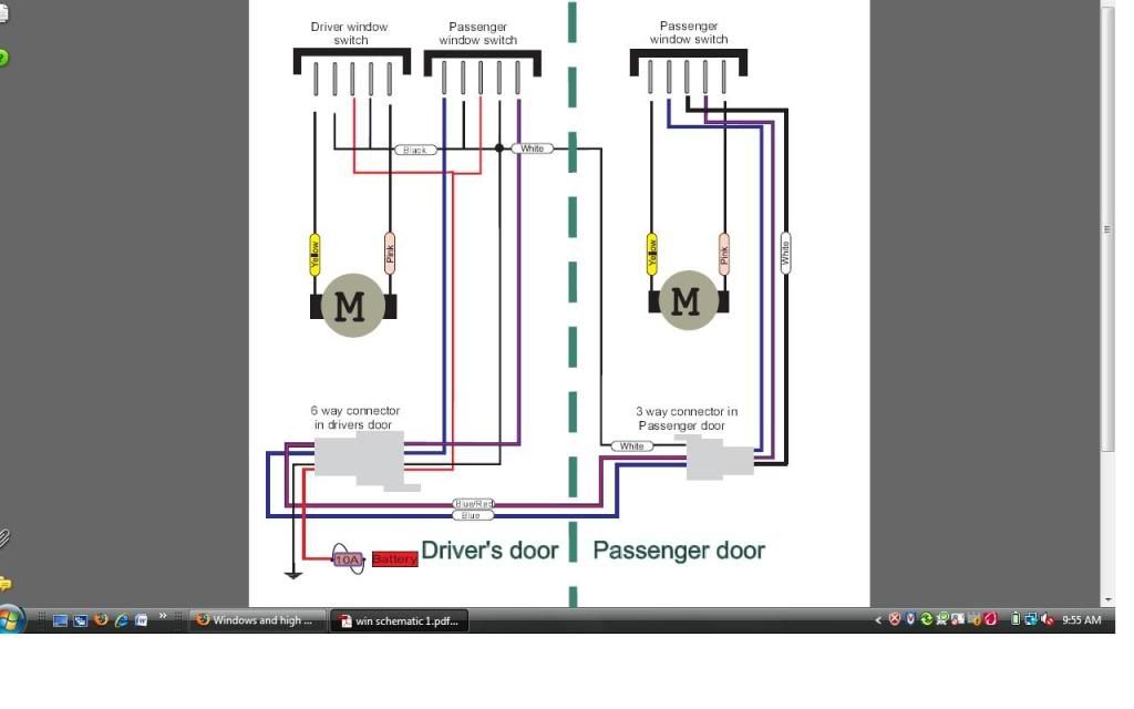
From what I can tell, the kit you have operates nothing like the factory one, so trying to tie in the factory switches with the aftermarket switch might put power on both sides of the motors.
This is what you would need to have :

If you look at the diagram above, the power distribution is much different than the factory method.
Obviously you need to check the polarity on the motors when you hook them up, so the button direction is sync'd with the motor direction. If they work reverse, just swap the pink and yellow wires on the motor to the switch.
This is what you would need to have :
If you look at the diagram above, the power distribution is much different than the factory method.
Obviously you need to check the polarity on the motors when you hook them up, so the button direction is sync'd with the motor direction. If they work reverse, just swap the pink and yellow wires on the motor to the switch.
Last edited by SSCULLY; Dec 22, 2009 at 01:41 PM. Reason: add in motor poarity line
Thread Starter
|
Technical Article Contributor
Joined: Feb 2008
Posts: 8,673
Likes: 0
From: Rosenberg/Baytown TX
Ok I'll try that later tonight but what are the wires above the driver switch? Is that just the power? Should I still use a relay forthe power source or just fused to the battery
Technical Article Contributor
Joined: Jun 2002
Posts: 10,511
Likes: 10
From: Under the flightpath of old ORD 22R
Without the power windows already installed, you might not have the accessory delay relay installed, that would have it operate until the doors open.
Maybe check the fuse panel for the accessory delay relay, to see if you can use this to trigger the power for the power window relay.
The other Light Blue w/ Red is the instrument illumination.
Thread Starter
|
Technical Article Contributor
Joined: Feb 2008
Posts: 8,673
Likes: 0
From: Rosenberg/Baytown TX
didnt have time to try it tonight since it was raining. but i like the idea of having it triggered by the acc power
Trending Topics
Technical Article Contributor
Joined: Jun 2002
Posts: 10,511
Likes: 10
From: Under the flightpath of old ORD 22R
When you get a chance, check the cab fuse panel, to see if you have Relay 5 installed.
This is the accessory delay relay. If this is not installed, we might still be able to use this to trigger the external relay, if the pin for the coil has a terminal in it.
The power to the accessory delay relay is from the battery saver relay, and the ground to the coil is from the GEM.
1. Check with a flash light, to see if there is a metal pin connector in the slots for the relay.
2. Pin 86 ( in the diagram below ) is the one that should have ground on it when you turn the key on, and when you open the door, ground should be gone. You can test this with a meter using ohms to ground, or to the cigar lights power pin in the center.
Watch the pin orientation

Make sure the function is only relying on the ground side, not power to be switched by the battery saver relay.
If power is being switched by the battery saver relay alone, could use that as the trigger for the relay coil.
This is the accessory delay relay. If this is not installed, we might still be able to use this to trigger the external relay, if the pin for the coil has a terminal in it.
The power to the accessory delay relay is from the battery saver relay, and the ground to the coil is from the GEM.
1. Check with a flash light, to see if there is a metal pin connector in the slots for the relay.
2. Pin 86 ( in the diagram below ) is the one that should have ground on it when you turn the key on, and when you open the door, ground should be gone. You can test this with a meter using ohms to ground, or to the cigar lights power pin in the center.
Watch the pin orientation
Make sure the function is only relying on the ground side, not power to be switched by the battery saver relay.
If power is being switched by the battery saver relay alone, could use that as the trigger for the relay coil.
Thread Starter
|
Technical Article Contributor
Joined: Feb 2008
Posts: 8,673
Likes: 0
From: Rosenberg/Baytown TX
well i dont have relay 5 but from what i can tell there are metal pieces in the slots. (the dash was getting in the way but relay 3 and 4 which are not present have them)
im still lost on how i would be wiring it up using this relay
im still lost on how i would be wiring it up using this relay
Technical Article Contributor
Joined: Jun 2002
Posts: 10,511
Likes: 10
From: Under the flightpath of old ORD 22R
You are not using the relay 5, but what you need to check is if the GEM is switching the ground to the relay coil ( i.e. make sure the wiring is in there, and connected to the GEM ).
The GEM knows to shut off the accessory delay, and does this by switching ground.
The battery saver can also do this by switching power ( took a look, this is the function in the 98 MY from what I have found ).
Normally a relay coil is controlled by switching power, but in your case the GEM switches ground. This functions the same, the coil shuts off, and opens the Normally Open contacts on the relay.
This is what it would look like

When you take a meter to check to ground, check both 85 & 86, just to be sure. One of them is to be on when the key is in the run / accy position, or any time after the key is in this position, up to when the door opens.
The GEM knows to shut off the accessory delay, and does this by switching ground.
The battery saver can also do this by switching power ( took a look, this is the function in the 98 MY from what I have found ).
Normally a relay coil is controlled by switching power, but in your case the GEM switches ground. This functions the same, the coil shuts off, and opens the Normally Open contacts on the relay.
This is what it would look like
When you take a meter to check to ground, check both 85 & 86, just to be sure. One of them is to be on when the key is in the run / accy position, or any time after the key is in this position, up to when the door opens.
Thread Starter
|
Technical Article Contributor
Joined: Feb 2008
Posts: 8,673
Likes: 0
From: Rosenberg/Baytown TX
ok that makes sense, now my only question is how will i tie into the 85 or 86 ground. might have a better idea in day light. should i be able to access it from the back?
Technical Article Contributor
Joined: Jun 2002
Posts: 10,511
Likes: 10
From: Under the flightpath of old ORD 22R
This way you are not moving the CJB & GEM around, which could work the connectors loose and cause you grief later, and the GEM supplied ground is not a wire, but actually from the connector to the slot all metal I think.
You would have to tear into the CJB quite a bit to find out, and I think it would be for not.
Thread Starter
|
Technical Article Contributor
Joined: Feb 2008
Posts: 8,673
Likes: 0
From: Rosenberg/Baytown TX
so when im testing the pins what output should i be looking for on my multimeter??
and ill only have to tear into stuff if i cant get to it from the front correct.
and ill only have to tear into stuff if i cant get to it from the front correct.
Technical Article Contributor
Joined: Jun 2002
Posts: 10,511
Likes: 10
From: Under the flightpath of old ORD 22R
With the GEM providing ( and removing ) ground a quick test is ohms to another ground source.
Easy one is ground on the cigar lighter ( make sure not to stick the probe in too far with it set to ohms ).
Don't think the hood latch bracket is a good ground, could be on the 98. My 2001 it was not.
Ground with the key in accessory / run position. With the door closed after having the key on, it should be on for ~ 10 min after that, or until the door opens.
If the pins are not in the slot, then the remainder of the circuit to the GEM bolted to the back of the CJB is not going to be there either.
The GEM to CJB connectors are right on the back of the CJB, and the GEM bolts right to it. The CJB / GEM come out as 1 unit when unbolted from the dash mounts.
If you cannot find the accessory delay ground from the GEM, going to have to go the route of hot in accessory / run position ( the add-a-fuse in the radio slot to trigger the relay the "normal" way ).
Thread Starter
|
Technical Article Contributor
Joined: Feb 2008
Posts: 8,673
Likes: 0
From: Rosenberg/Baytown TX
can i just use my test light to check for the ground is working or not?? it seems simpler to me. if i cant get to it im just gonna fuse into the acc power on the radio. hope to get this tested tomorrow and maybe installed.