
Center Console Sub Enclosure Build


Thread Starter
|
Technical Article Contributor
Joined: Mar 2008
Posts: 2,268
Likes: 2
From: Rural NE
Center Console Sub Enclosure Build
Day 1:
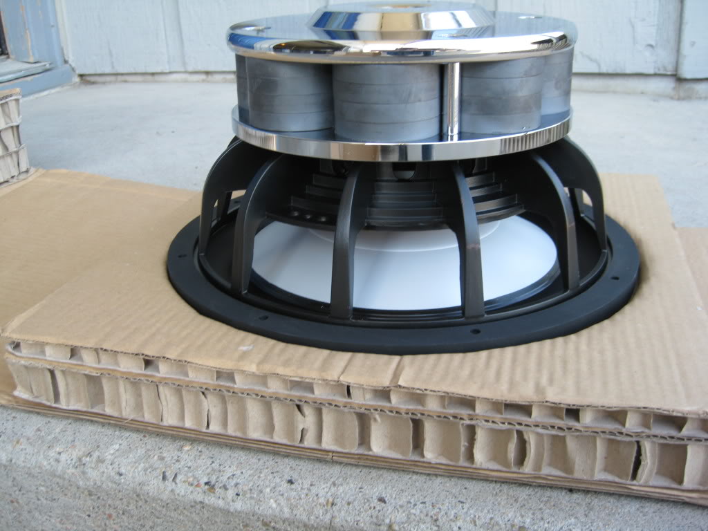
Well, I came across a sub for a price that I simply could not pass up. I ordered a DIYMA Reference 12. This sub has a massive magnet, weighing in at just under 40 pounds. The sub unfortunately has a mount depth of 6.3”, an x max just short of 1”, and needs about a ½” behind the pole vent on the motor. That means I need a min of 7.8” which for those of you keeping tally means I will not in anyway shape or form be able to fit this sub under my seat, thus leading me to build a subwoofer enclosure out of the center console.
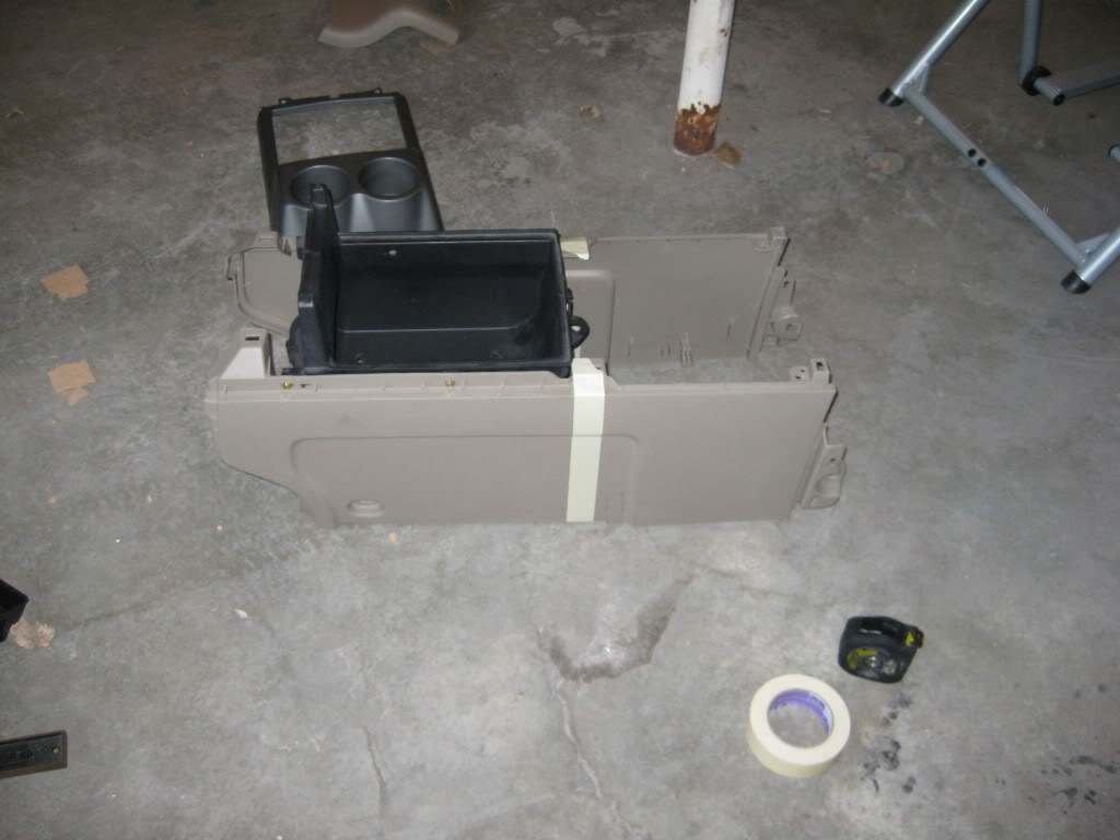
The tear out of the center console was pretty straight forward. The base around the shifter and cup holders, is held on with some simple pressure clips and pops right off with little effort.
The pile:
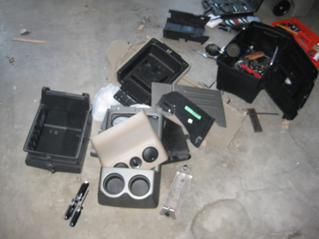
Next you will want to unscrew the center console lid from the black tray (requires a torx but I forgot the size of it).
After you have the lid off you can now undo a few bolts (7mm, I believe) and take the gray trim ring off leaving just the tan sides and the black console tray in place.
The black tray will now have a few more bolts holding it to the walls of the console. There are 4 more bolts on the bottom of this black tray as well.
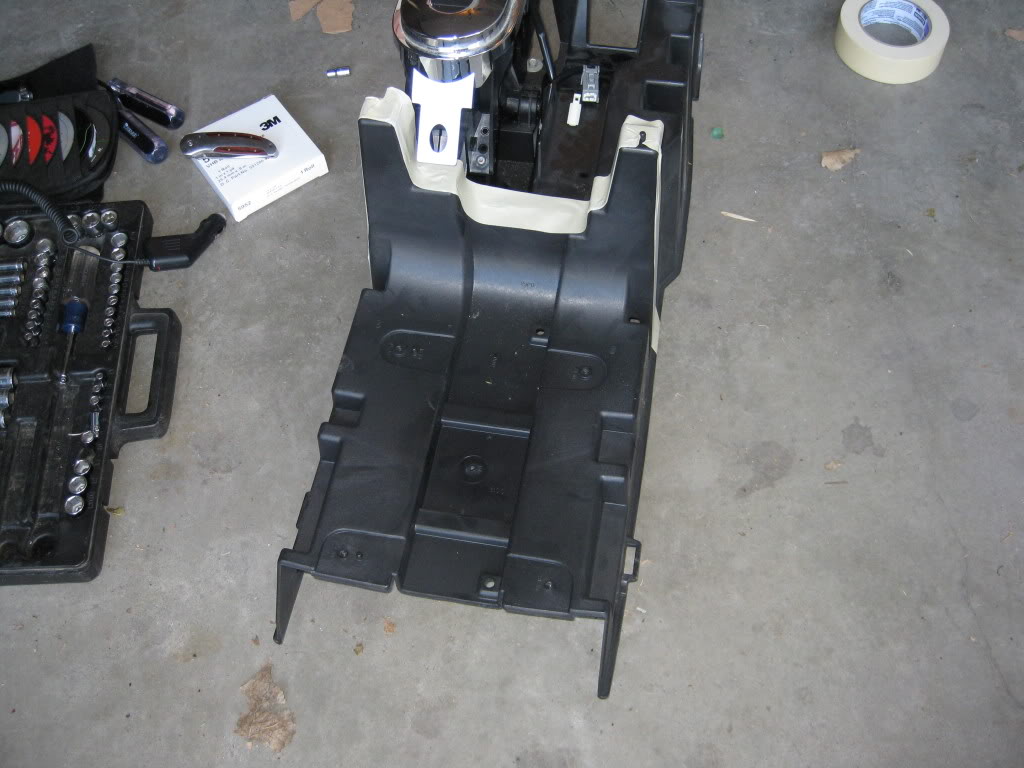
Now you will lift the black console piece out of the way. The tan piece that holds the rear air vents and 12v source is held in place with simple pressure clips and will pop off very easily. Be sure to disconnect the wiring harness to it before you try removing it completely.
Then, there are a four 10 mm bolts left holding the tan walls together. There are two located at the back of the console; these can be accessed by sliding your seats all the way forward. There are two more left at the front of the console behind a two trim panels you will have to remove to get to them.
Well, I came across a sub for a price that I simply could not pass up. I ordered a DIYMA Reference 12. This sub has a massive magnet, weighing in at just under 40 pounds. The sub unfortunately has a mount depth of 6.3”, an x max just short of 1”, and needs about a ½” behind the pole vent on the motor. That means I need a min of 7.8” which for those of you keeping tally means I will not in anyway shape or form be able to fit this sub under my seat, thus leading me to build a subwoofer enclosure out of the center console.
The tear out of the center console was pretty straight forward. The base around the shifter and cup holders, is held on with some simple pressure clips and pops right off with little effort.
The pile:
Next you will want to unscrew the center console lid from the black tray (requires a torx but I forgot the size of it).
After you have the lid off you can now undo a few bolts (7mm, I believe) and take the gray trim ring off leaving just the tan sides and the black console tray in place.
The black tray will now have a few more bolts holding it to the walls of the console. There are 4 more bolts on the bottom of this black tray as well.
Now you will lift the black console piece out of the way. The tan piece that holds the rear air vents and 12v source is held in place with simple pressure clips and will pop off very easily. Be sure to disconnect the wiring harness to it before you try removing it completely.
Then, there are a four 10 mm bolts left holding the tan walls together. There are two located at the back of the console; these can be accessed by sliding your seats all the way forward. There are two more left at the front of the console behind a two trim panels you will have to remove to get to them.
Last edited by Bluejay; Apr 28, 2009 at 11:26 AM.
Thread Starter
|
Technical Article Contributor
Joined: Mar 2008
Posts: 2,268
Likes: 2
From: Rural NE
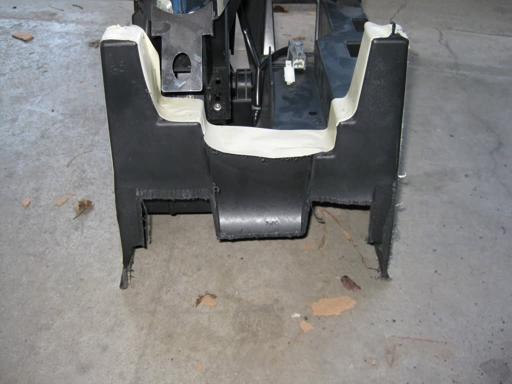
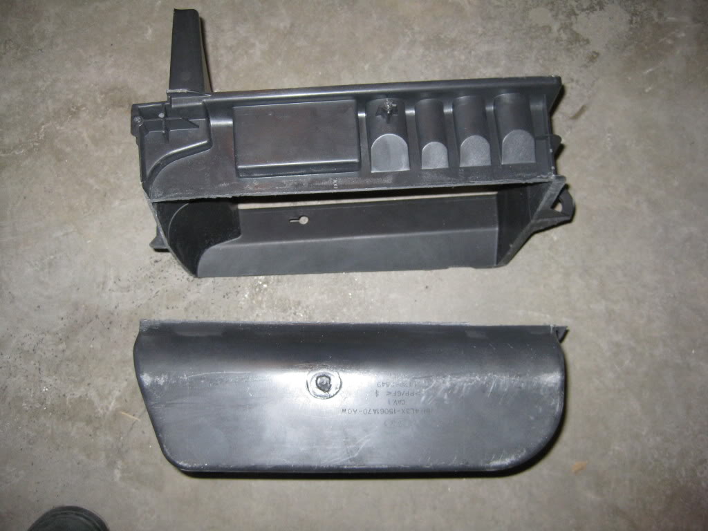
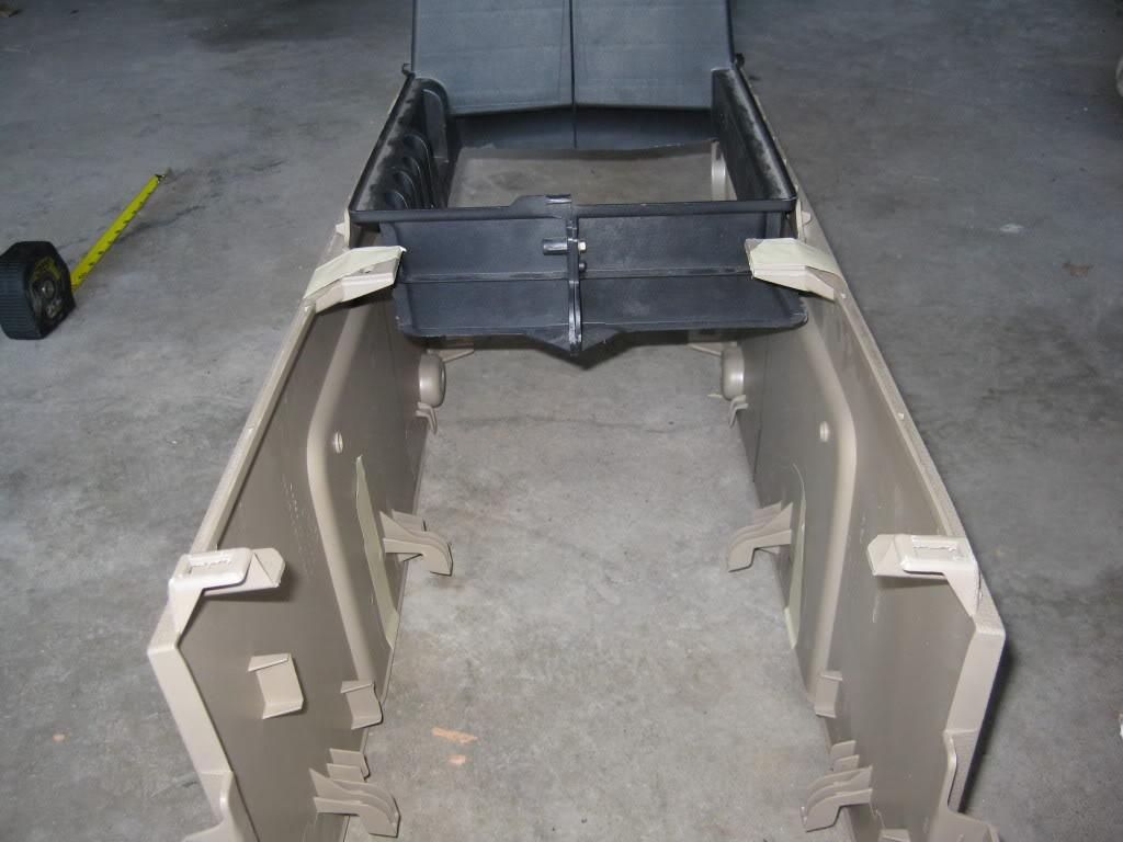
Now that the console is out of the truck, I needed to remove the rear air duct. There are a few more bolts that need to be pulled out of the remaining console “guts”. After taking out the guts of the console I decided that I would need to cut down the main piece so that I can get the proper clearance for the new sub.
The mark up:
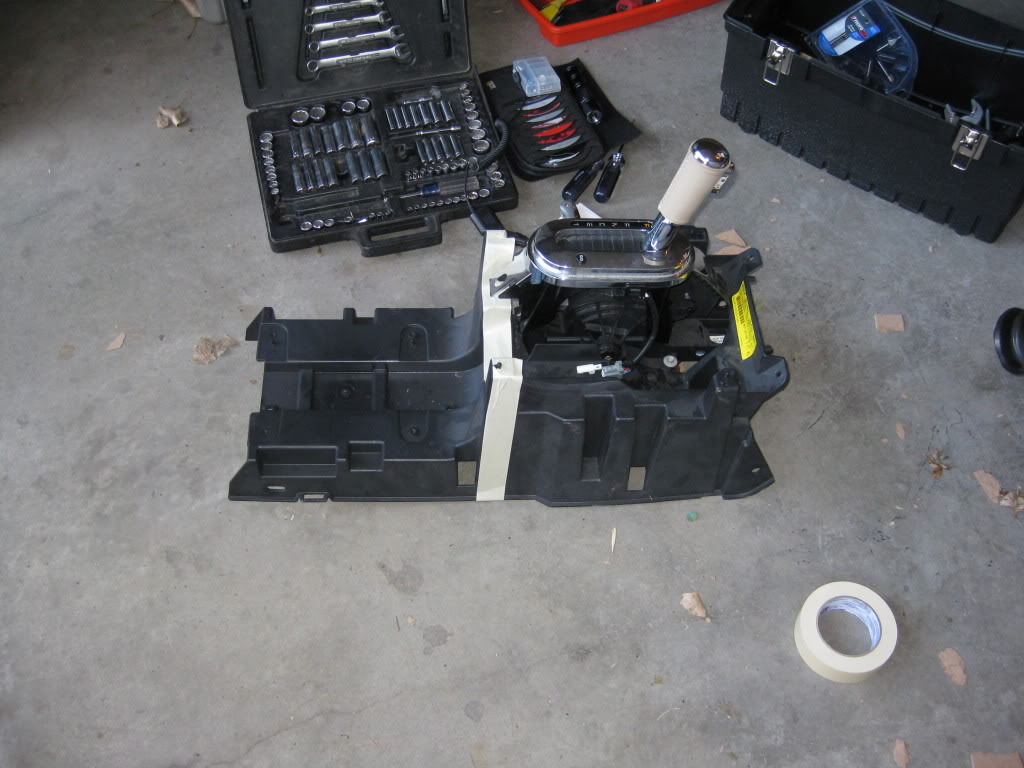
The separation:
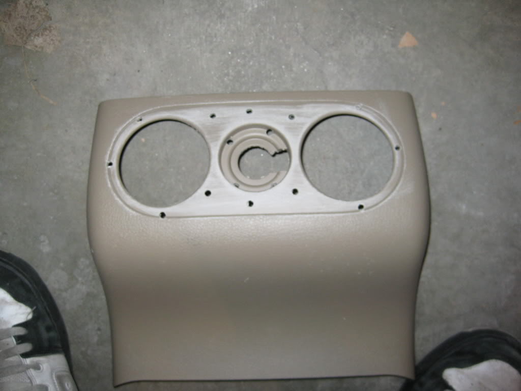
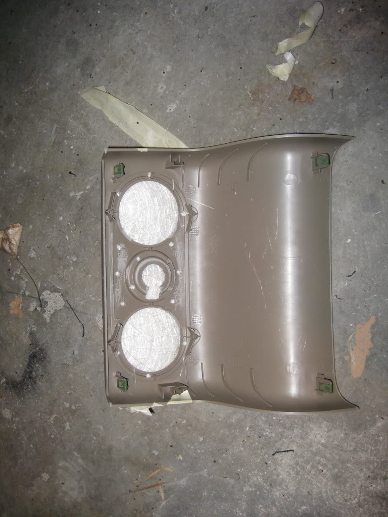
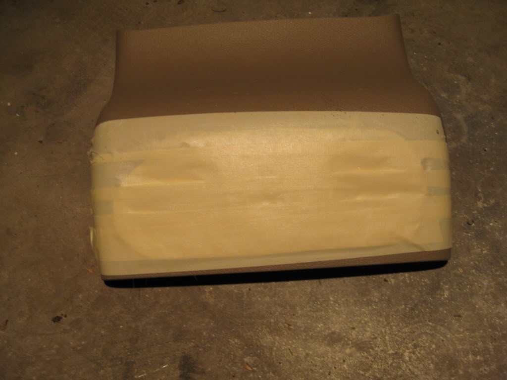
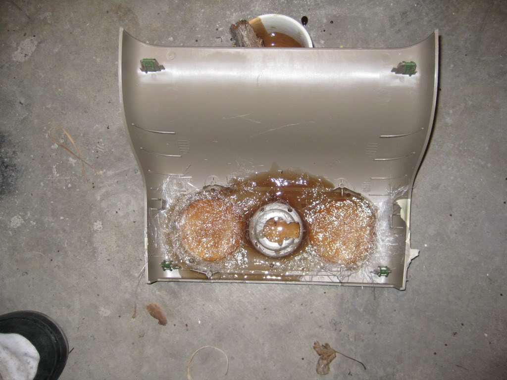
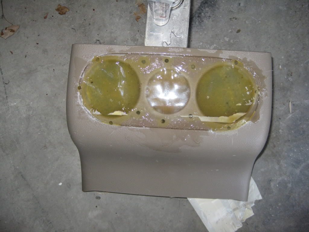
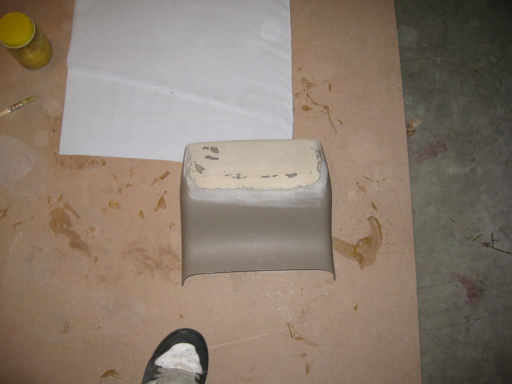
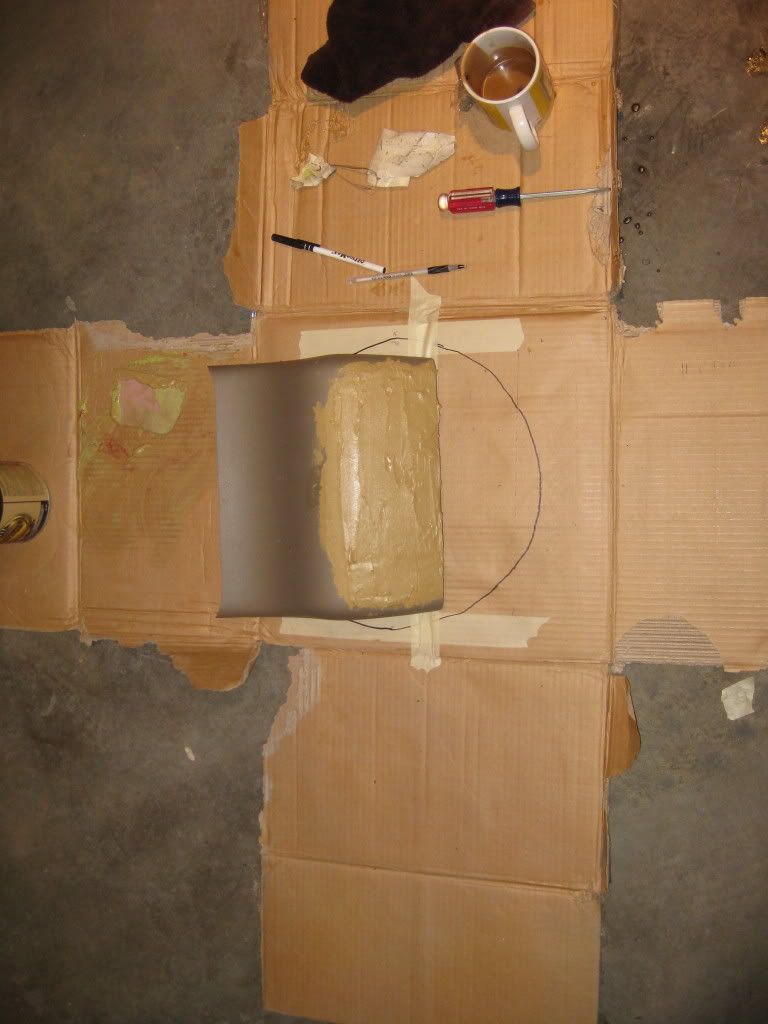
Since I would no longer be using the rear air, I decided I would go ahead and delete the rear air vents along with the rear 12v source. I drilled small holes in the surface of the trim panels and sanded it down to make sure the fiberglass would properly bond to the panel. I will be wrapping this piece with tan leather once I apply a coat of body filler and sand it down smooth.
The piece:
Ready for resin:
Resin applied:
The mark up:
The separation:
Since I would no longer be using the rear air, I decided I would go ahead and delete the rear air vents along with the rear 12v source. I drilled small holes in the surface of the trim panels and sanded it down to make sure the fiberglass would properly bond to the panel. I will be wrapping this piece with tan leather once I apply a coat of body filler and sand it down smooth.
The piece:
Ready for resin:
Resin applied:
Last edited by Bluejay; Apr 28, 2009 at 11:28 AM.
Thread Starter
|
Technical Article Contributor
Joined: Mar 2008
Posts: 2,268
Likes: 2
From: Rural NE
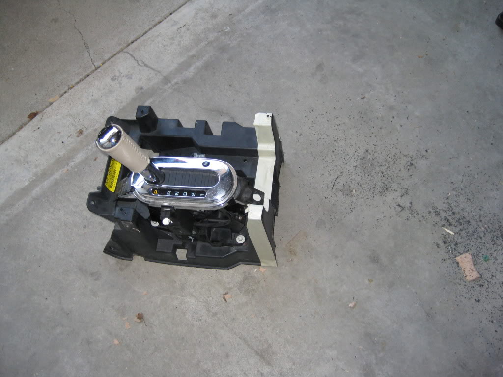
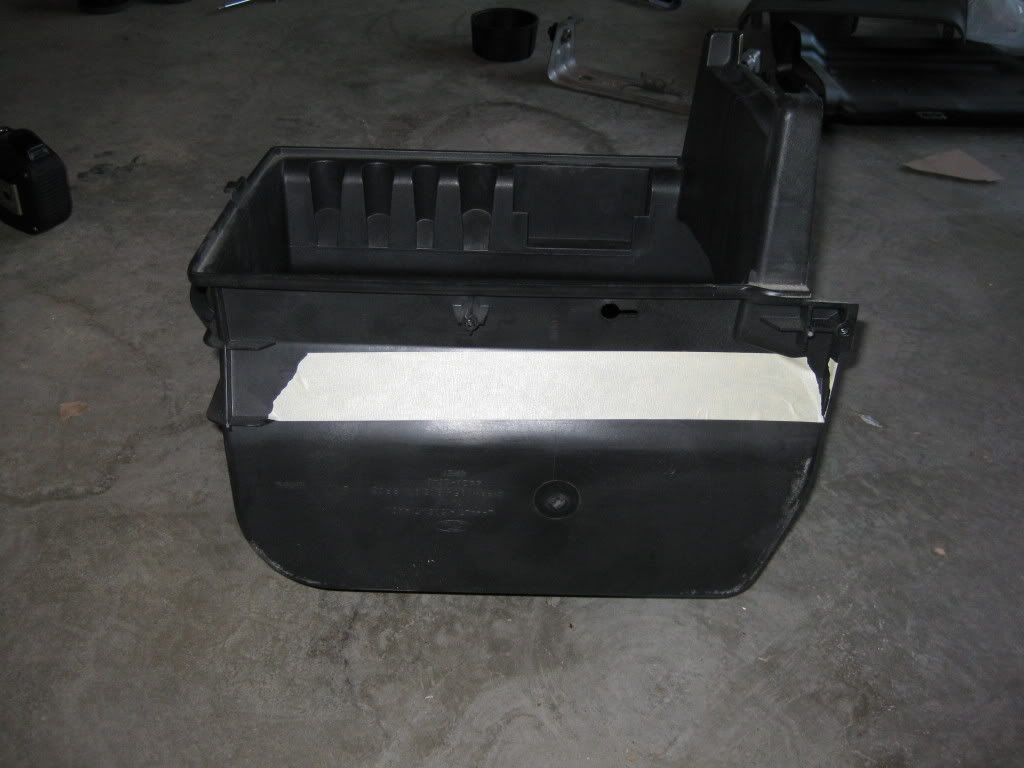
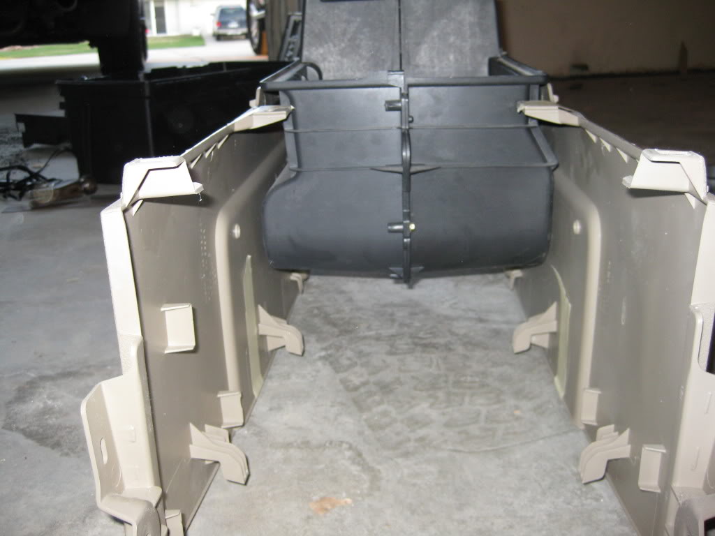
Next I figured out how much of the bottom to cut off of the black console piece. I will be putting a .375” thick piece of acrylic in the bottom so that I can show off the sub once it is installed. I will also be adding a few leds to light the area up once I figure out where I want to mount them.
The markup:
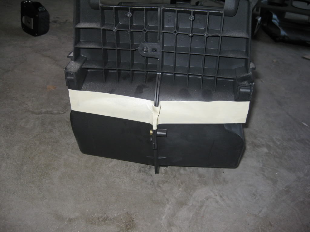

The separation:
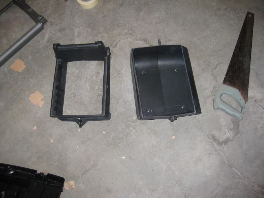
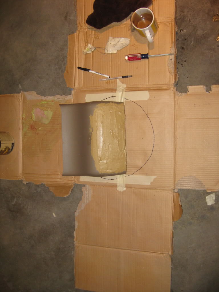
I am also making a fiberglass plug to stop the airflow to the now deleted flow through console.
The markup:
The separation:
I am also making a fiberglass plug to stop the airflow to the now deleted flow through console.
Thread Starter
|
Technical Article Contributor
Joined: Mar 2008
Posts: 2,268
Likes: 2
From: Rural NE
Day 2:
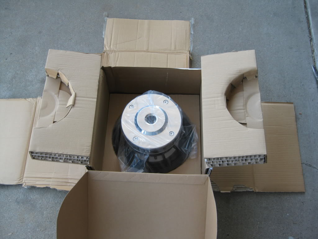
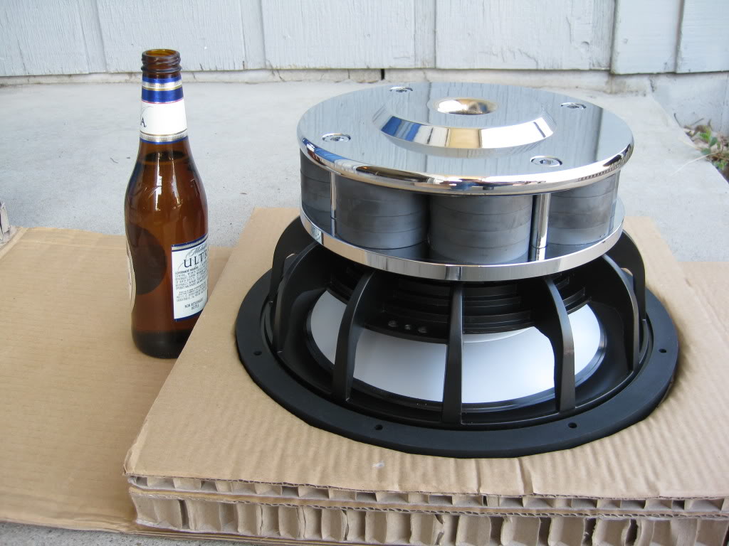
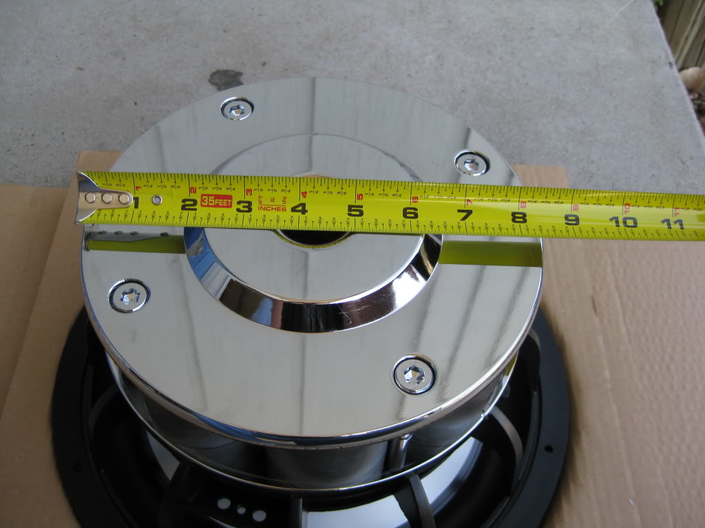
Well, today I received my driver in the mail. My first impressions of the sub are simply wow. I knew coming in to buying this sub that it was going to be big but dang this thing actually fills out the center console perfectly. Here are a few pics of it:
Here it is just waiting to be opened:
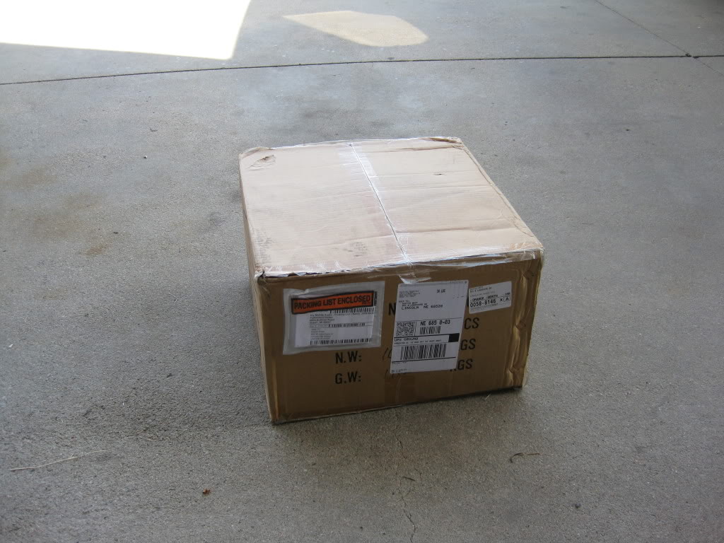
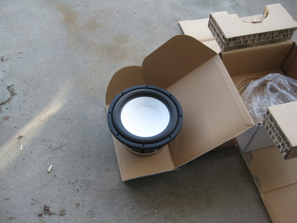
The DIYMA Reference 12:
Scale reference:
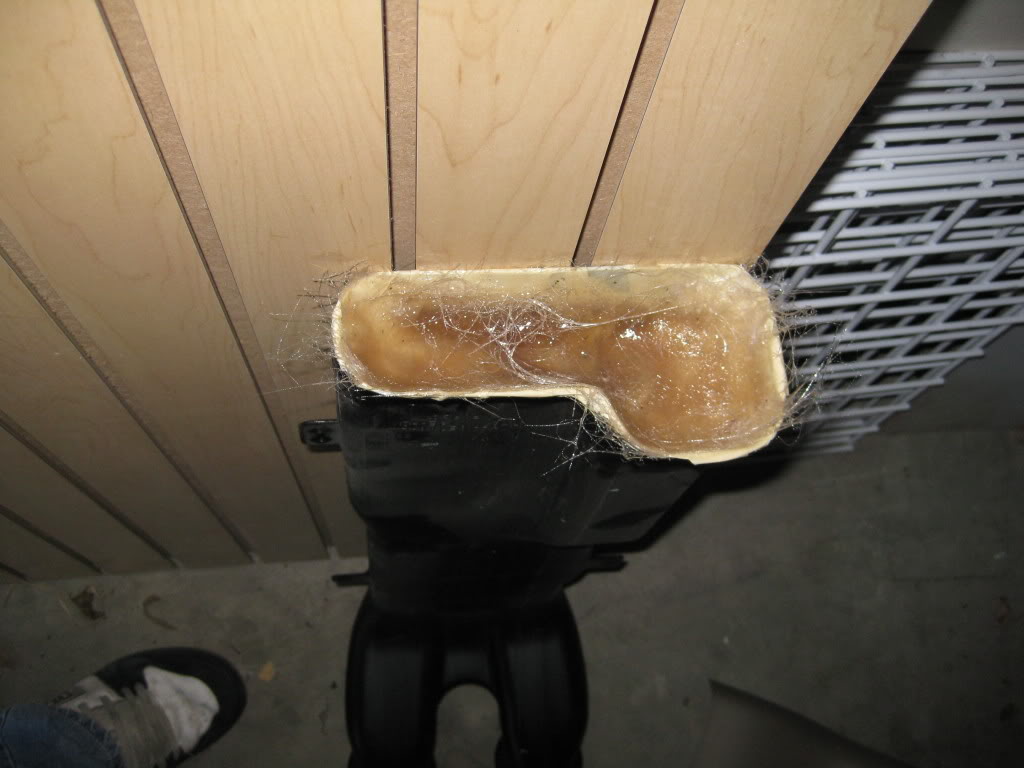
I managed to go get more resin last night so I managed to get the rear air vent plug started and I got one more layer of glass on the rear air delete panel as well. Tonight I will be getting that smoothed over with body filler and have it sanded down for tomorrow so I can get it wrapped in leather.
Rear air plug: (glass is sloppy in this pic I smoothed it out later on)
Rear air delete:
Well, today I received my driver in the mail. My first impressions of the sub are simply wow. I knew coming in to buying this sub that it was going to be big but dang this thing actually fills out the center console perfectly. Here are a few pics of it:
Here it is just waiting to be opened:
The DIYMA Reference 12:
Scale reference:
I managed to go get more resin last night so I managed to get the rear air vent plug started and I got one more layer of glass on the rear air delete panel as well. Tonight I will be getting that smoothed over with body filler and have it sanded down for tomorrow so I can get it wrapped in leather.
Rear air plug: (glass is sloppy in this pic I smoothed it out later on)
Rear air delete:
Last edited by Bluejay; Apr 28, 2009 at 11:36 AM.
Thread Starter
|
Technical Article Contributor
Joined: Mar 2008
Posts: 2,268
Likes: 2
From: Rural NE
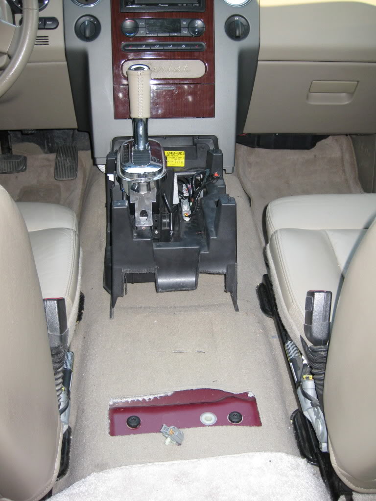
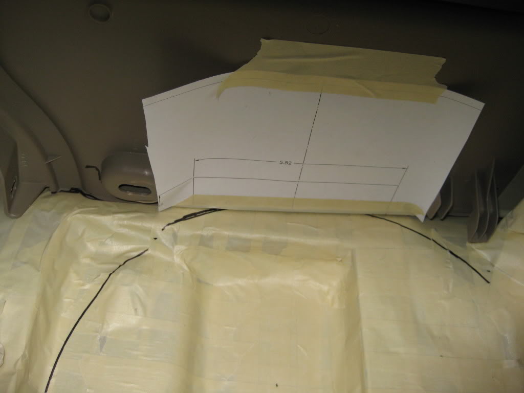
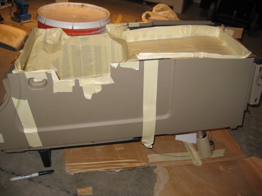
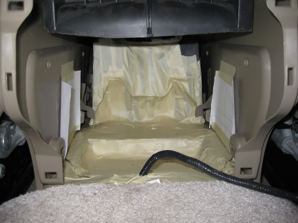
I am getting ready to make the tub for the enclosure, and here is the area prepped for the fiberglass. I won’t be starting this part until this weekend as I want to be able to have the windows and doors all open on the truck so I don’t get fumed out.
Mark up:
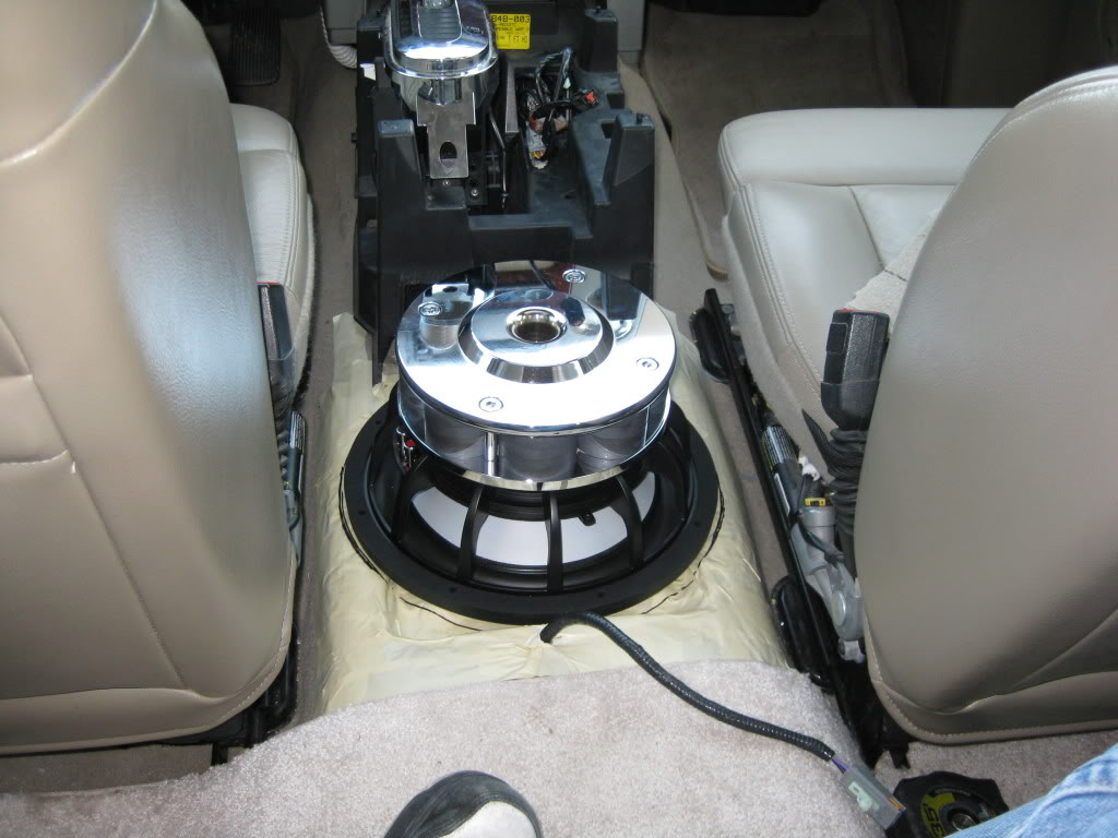
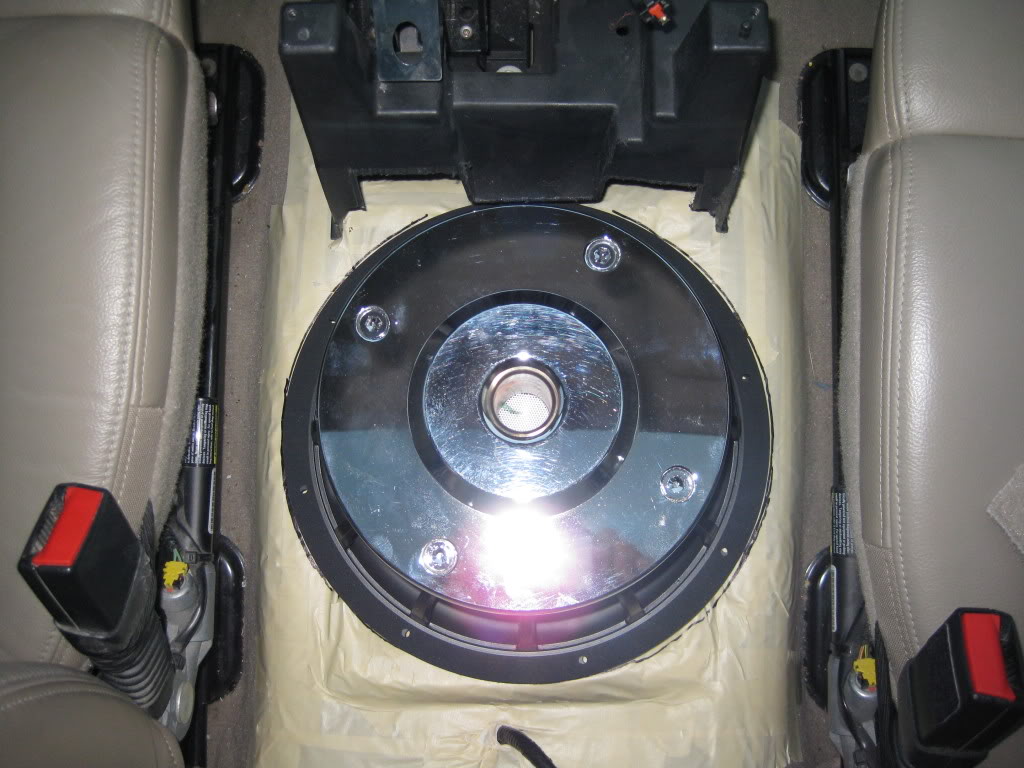
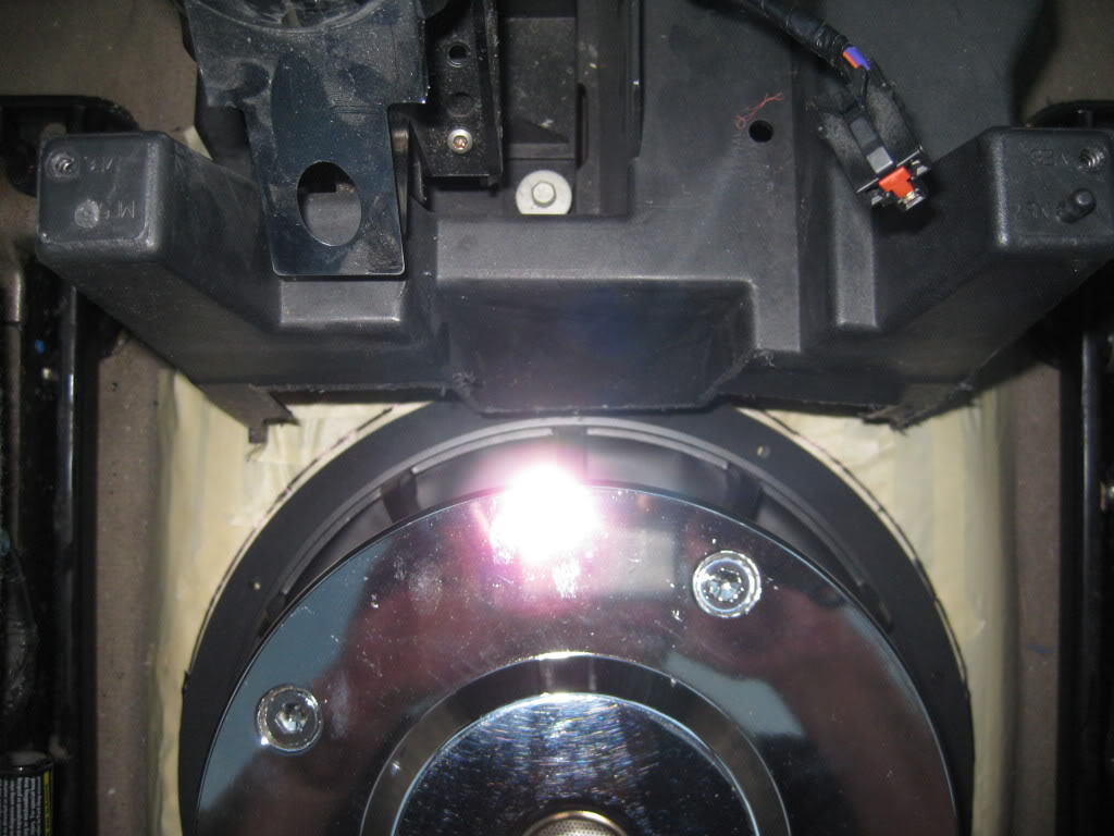
Here are pics of where the sub will be sitting in the truck:
I also have some acrylic being cut so I can make a window in the bottom of the console so that you can see this sub after the install.
Misc pics:
Mount area where sub will be sitting:
Mark up:
Here are pics of where the sub will be sitting in the truck:
I also have some acrylic being cut so I can make a window in the bottom of the console so that you can see this sub after the install.
Misc pics:
Mount area where sub will be sitting:
Last edited by Bluejay; Apr 28, 2009 at 11:38 AM.

Technical Article Contributor
Joined: Oct 2005
Posts: 1,616
Likes: 0
From: Concordia, MO


Trending Topics
Thread Starter
|
Technical Article Contributor
Joined: Mar 2008
Posts: 2,268
Likes: 2
From: Rural NE
Day 3:
Well tonight, I went at it with a reckless abandon. I did not have any interruptions and managed to get a decent amount of work done.
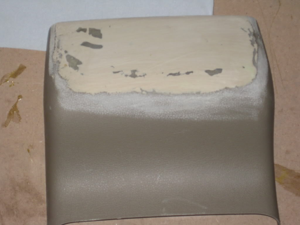
I started off by applying the body filler so that had time to dry while I was working on the fiberglass.
Body filler applied:
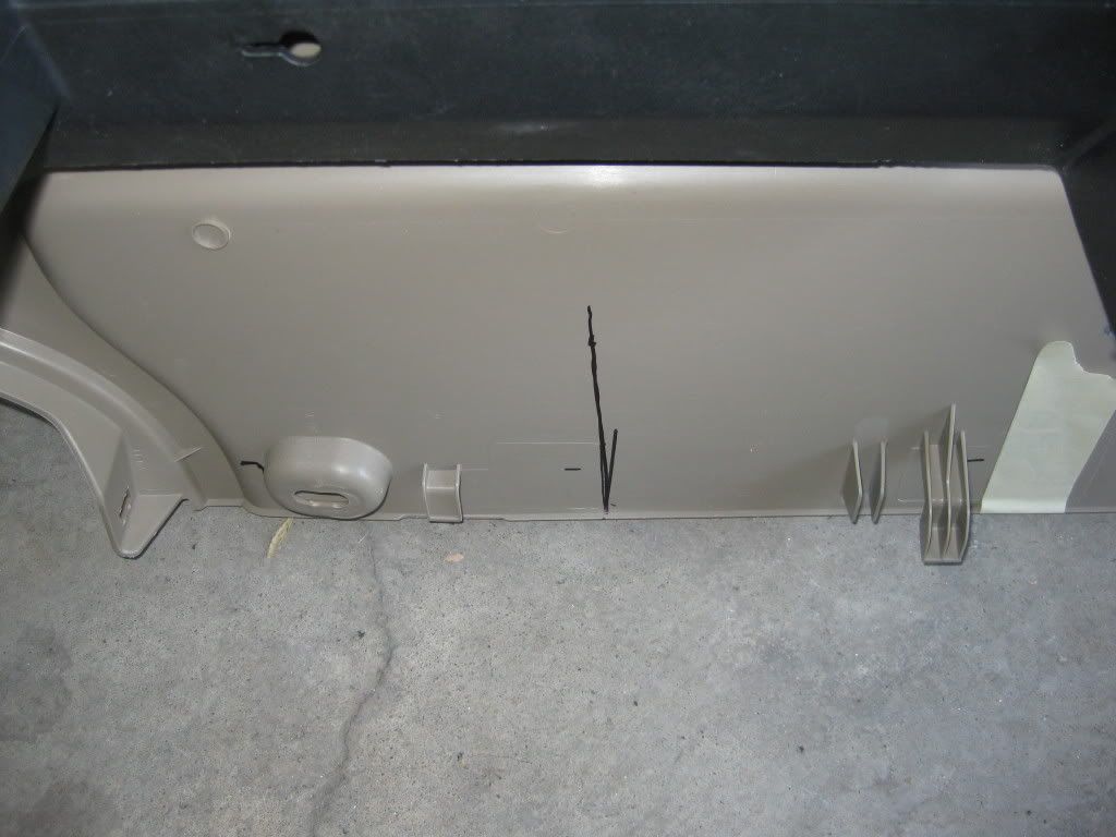
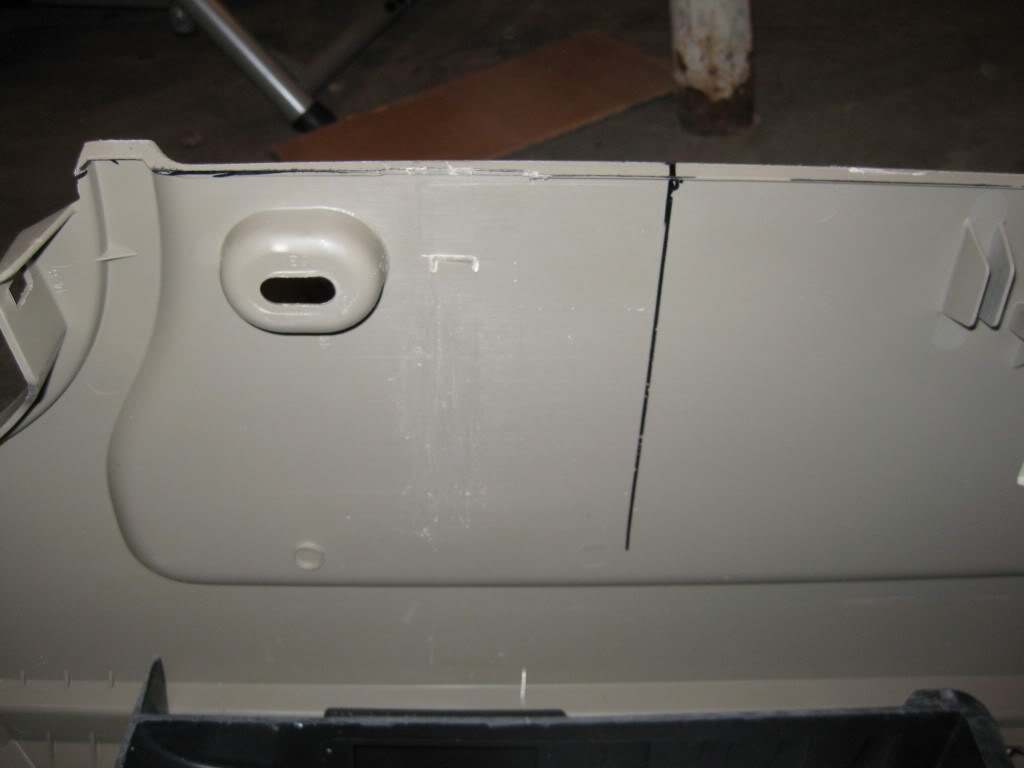
Next on the list was to mark off were I was going to need to make the console wider so I took the console back to the truck and got the center lines in and marked.
I then removed a tab on each side of the console that was going to get in the way.
Tab On: (The tab is located next to the oval)
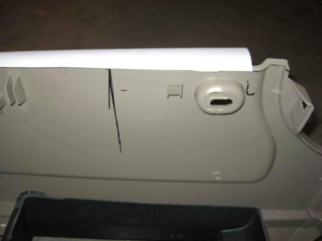
Tab Off:
Well tonight, I went at it with a reckless abandon. I did not have any interruptions and managed to get a decent amount of work done.
I started off by applying the body filler so that had time to dry while I was working on the fiberglass.
Body filler applied:
Next on the list was to mark off were I was going to need to make the console wider so I took the console back to the truck and got the center lines in and marked.
I then removed a tab on each side of the console that was going to get in the way.
Tab On: (The tab is located next to the oval)
Tab Off:
Thread Starter
|
Technical Article Contributor
Joined: Mar 2008
Posts: 2,268
Likes: 2
From: Rural NE
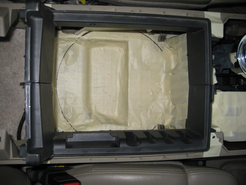
I then cut my plexiglass, and got the window arranged in the box.
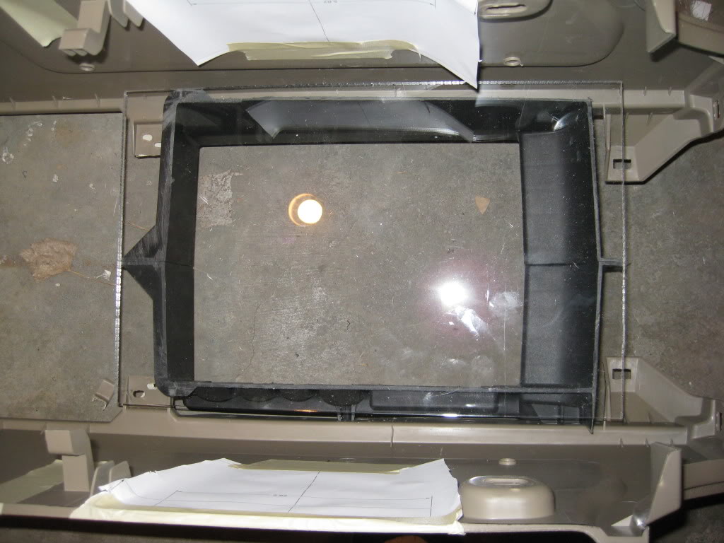
Next I assembled the entire console so I could make the top half of my sub box.
I cut out the widening slots to allow room for the ring.
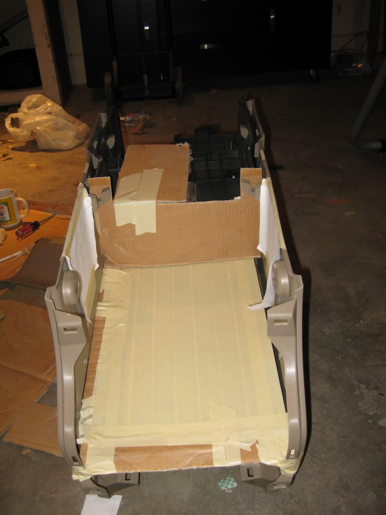
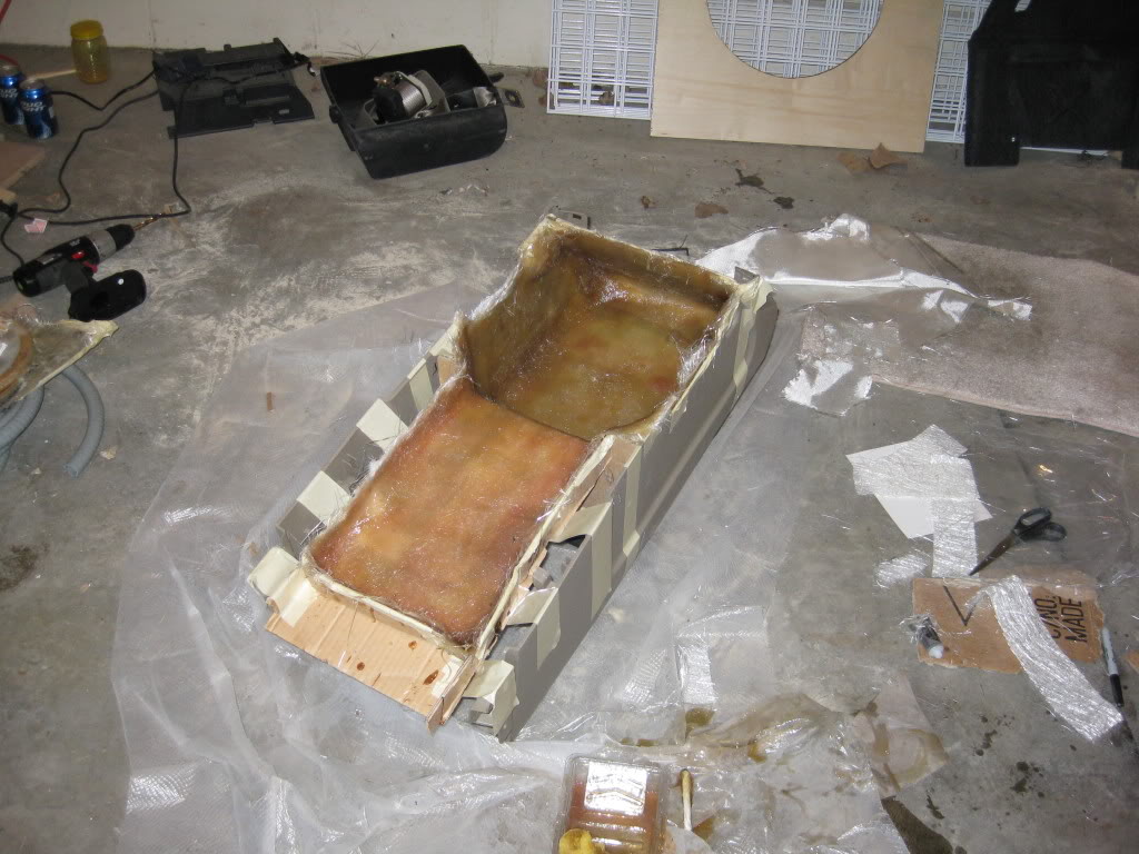
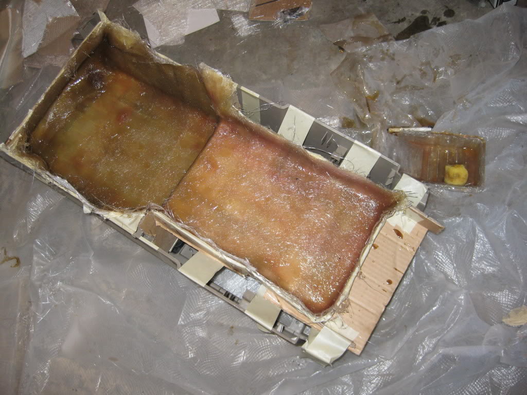
After all that I lined everything with tape and cardboard so that I could start the glass work.
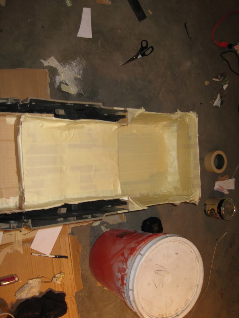
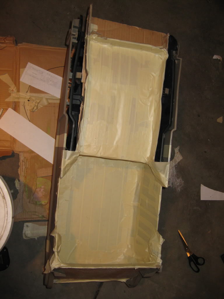
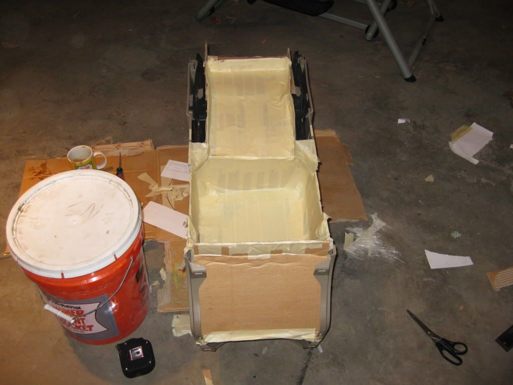
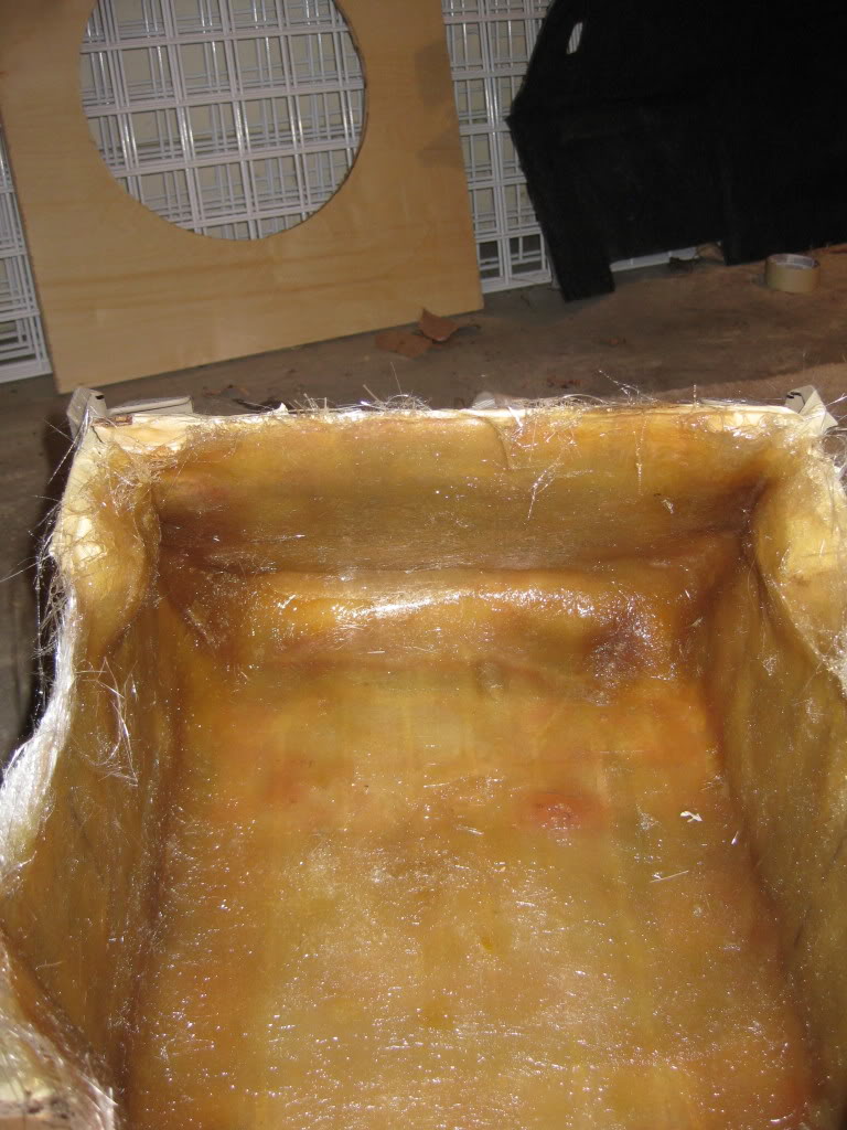
Resin applied
A roller is your friend when fiber glassing that is all I can say. I don’t know why but in this picture it looks like there are a few air bubbles but there are zero in the glass, so no worries there.
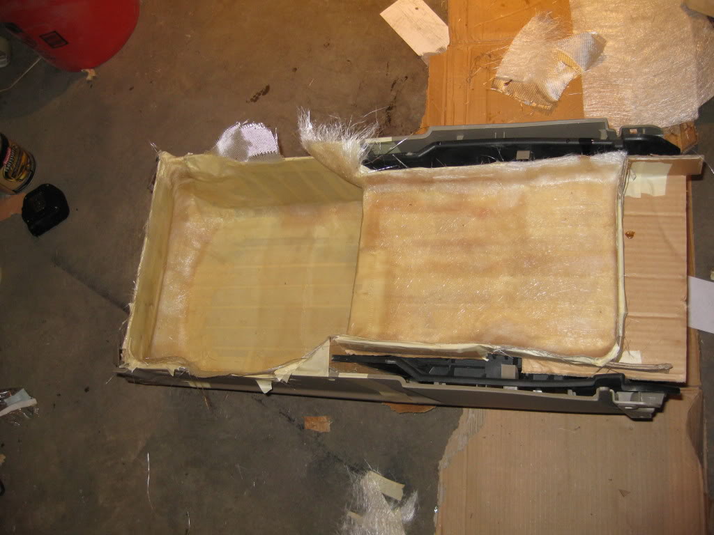
After I got it all covered in resin and 3 layers of glass I let that dry so I could come back to the rear air delete. I got it all sanded down and prepped for the vinyl and glue.
Next I assembled the entire console so I could make the top half of my sub box.
I cut out the widening slots to allow room for the ring.
After all that I lined everything with tape and cardboard so that I could start the glass work.
Resin applied
A roller is your friend when fiber glassing that is all I can say. I don’t know why but in this picture it looks like there are a few air bubbles but there are zero in the glass, so no worries there.
After I got it all covered in resin and 3 layers of glass I let that dry so I could come back to the rear air delete. I got it all sanded down and prepped for the vinyl and glue.
Thread Starter
|
Technical Article Contributor
Joined: Mar 2008
Posts: 2,268
Likes: 2
From: Rural NE
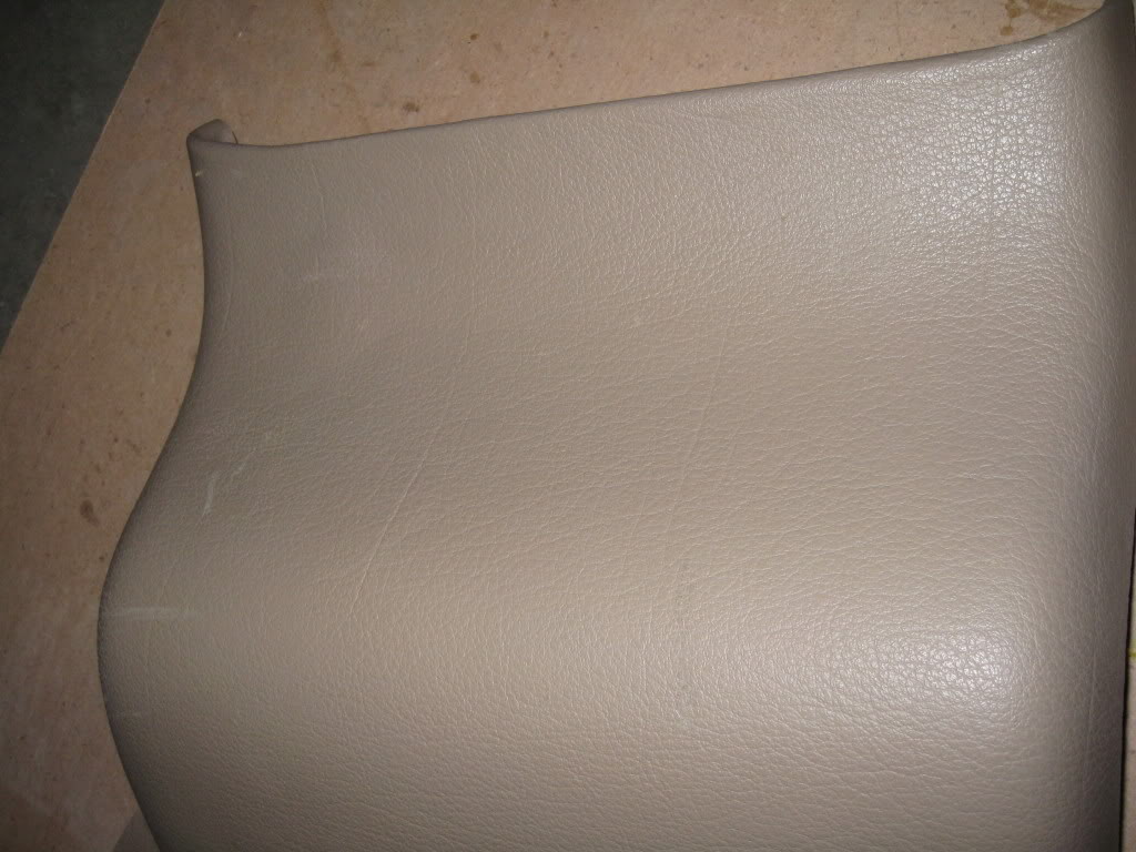
Well after about an hour of gluing, heating, and stretching I got the panel finished, sorry no pics of the stretching.
Finished rear air delete panel:
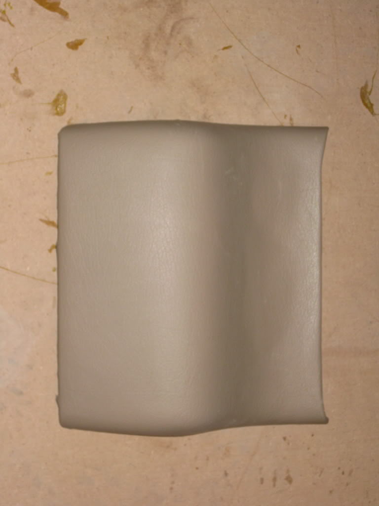
And lastly I took the shifter back to the truck and reassembled it so I could drive to work this morning and post this up.
Misc Pics:
Finished rear air delete panel:
And lastly I took the shifter back to the truck and reassembled it so I could drive to work this morning and post this up.
Misc Pics:
Technical Article Contributor
Joined: Oct 2005
Posts: 1,616
Likes: 0
From: Concordia, MO
Looks good, I guess? Never done that stuff before.
That coffee you are drinking looks NASTY!
I don't think you made it right.
That coffee you are drinking looks NASTY!
I don't think you made it right.
Thread Starter
|
Technical Article Contributor
Joined: Mar 2008
Posts: 2,268
Likes: 2
From: Rural NE
Thanks guys, I don't really have any pictures of things to show all I really got done was more layers of fiberglass I want to build this one up 15 to 20 layers. I did make progress and I got the big 3 upgrade done however. So I will hopefully have pics up later today, of the bottom half of this console build. stay tuned
Thread Starter
|
Technical Article Contributor
Joined: Mar 2008
Posts: 2,268
Likes: 2
From: Rural NE
Thanks, I like using evercoat products. I think the biggest thing is just to make sure all the air bubbles are out, they compromise the strength of the build. You can always trim that is the best part.
Well I did not get very much done this weekend with traveling for Easter, I will get the pictures I have uploaded tomorrow morning. I won't be able to work on it tonight either, but Tuesday I have reserved to get some major progress made. I am hoping to try and get all the layers of mat down on both pieces so I can focus on getting them bonded together.
Well I did not get very much done this weekend with traveling for Easter, I will get the pictures I have uploaded tomorrow morning. I won't be able to work on it tonight either, but Tuesday I have reserved to get some major progress made. I am hoping to try and get all the layers of mat down on both pieces so I can focus on getting them bonded together.
Thread Starter
|
Technical Article Contributor
Joined: Mar 2008
Posts: 2,268
Likes: 2
From: Rural NE
Day 5:
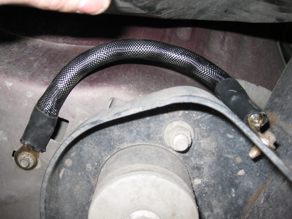
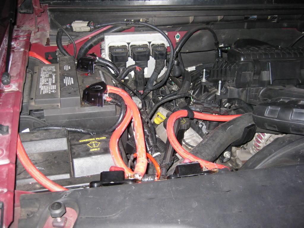
Well there has been a lot of work that has been accomplished off camera in the past couple days. I have managed to get my “big 4” ground and power cables in the engine bay done, along with making my (4) 20’ runs of speaker wire tech flexed and connectors soldered on. I have the main power cable ran to the back of the cab via caraflex non metallic conduit running under the cab, secured to the frame.
A few big 4 random pics:
Stock body to frame ground:
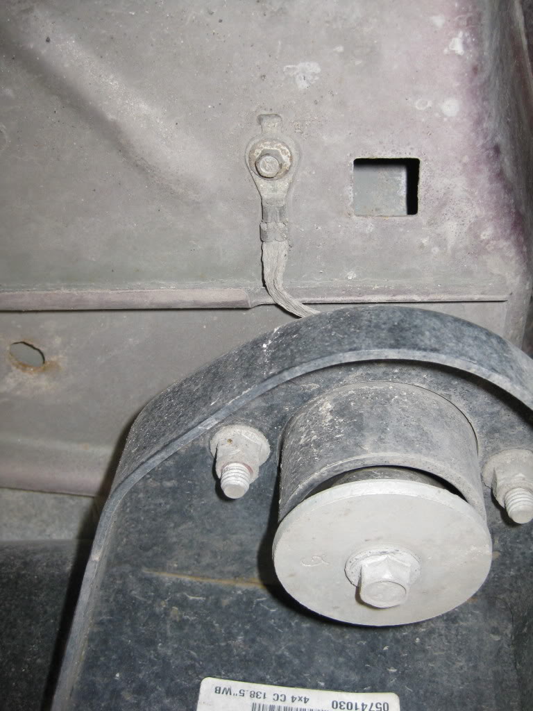
Upgraded 1/0 body to frame ground:
Shot of the engine bay:
Well over the past couple of days I have been working mainly on adding layers to the box. I have about 10 layers on the box. Things are coming together very nicely and I am starting to get antsy waiting for this thing to get finished.
Well there has been a lot of work that has been accomplished off camera in the past couple days. I have managed to get my “big 4” ground and power cables in the engine bay done, along with making my (4) 20’ runs of speaker wire tech flexed and connectors soldered on. I have the main power cable ran to the back of the cab via caraflex non metallic conduit running under the cab, secured to the frame.
A few big 4 random pics:
Stock body to frame ground:
Upgraded 1/0 body to frame ground:
Shot of the engine bay:
Well over the past couple of days I have been working mainly on adding layers to the box. I have about 10 layers on the box. Things are coming together very nicely and I am starting to get antsy waiting for this thing to get finished.