
Few more things for my truck...


I'm going to start a little write up and work on it over the week...
Overall the install was pretty straight forward ONCE I had a wiring diagram. This setup has NO check valves, so longer starts are normal. I am pleased so far the results of this unit. I highly suggest this install is for someone with good electrical and mechanical skills.If there are any errors in the pictures I apologize in advance.
For the install, I took off my bed. 6 bolts, 2 hoses, 3 7mm screws for the filler neck, and 2 connections out back for the lights. Don't forget to unhook the battery first. The factory FPDM is out back and the tank is located driver side center of the truck.

Here you can see the attached Kenne Bell boost a pump wired into the FPDM. You will need to cut and splice into this connector later on.

Before you remove anything from the tank, blow it off with high compressed air.

Now you must remove the fuel lines and electrical connections. To remove lines, you must either press in completely, or pull out a tab then press in. **note** There is a line IN the tank you must unhook also.

Next you will need to take off the ring that holds the assembly in place. To do this you need a screwdriver and a hammer. Don't be afraid to use some force in this process.
[IMG] [/IMG]

Now before you do anything else, blow off the area again of any loose dirt. You will need to disconnect one line that is inside the tank. Remove carefully. (sorry no picture)
You will need transfer the fuel level float sensor from your factory unit to the aftermarket Fore Precision Work's unit. This is a simple snap on, snap off operation. Disconnect the sensor's wire, DON'T CUT. Connect the wire from the factory level sensor to the wire on the aftermarket unit and use heat shrink to ensure a tight bond between the connection. You will also need to install your fuel pumps and hook them up to the existing wires on the unit. The pump wires will only go one way so it's dummy proof. Tighten hose clamps to the pump once they are installed in the unit. You must also attach a ground wire, just remove a screw and attach(see picture).


Now the unit is ready to install. When installing don't forget to hook up the in-tank line that you disconnected earlier.

You must also place the tab on the hat in the correct orientation. You will see an arrow on the tank(sorry no picture of arrow) Place the factory ring back on using a screwdriver and hammer.

Apparently, somewhere amongst the years, ford decided to change sizes of some lines. Included in the kit is an extra piece that allows you to use either of the lines. Remove the 2.5mm alan headed screws and replace. Snap your lines back on and you are finished with the physical install of the fuel hat setup itself.

**Note**This is where it will get real vague until I get some time to draw up a wiring diagram.
I installed the 2nd FPDM on the drive side frame rail near the factory FPDM. I drilled and tapped(6mm) the frame to use the supplied hardware. I also installed the two relays where the spare tires normally resides(mine has rides in my bed).


The two fuel pump 30amp breakers that come with the kit I mounted on the firewall with existing factory hardware. I made a small plate and bolted the breakers to it. I routed (2) 10 gauge wires from the batter to the bronze studs of the breakers. The supplied 10 gauge wire and looms travels from the "silver" stud of the breakers, through the cowl, down to the driver side frame rail to the back of the truck to the relays.

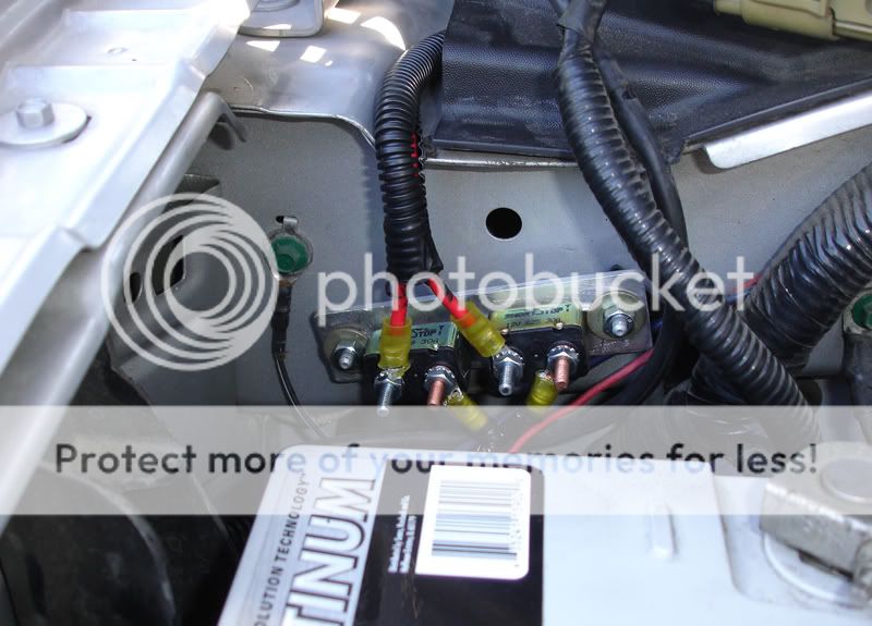

and just a picture of the fuel hat all wired up and complete..

Overall the install was pretty straight forward ONCE I had a wiring diagram. This setup has NO check valves, so longer starts are normal. I am pleased so far the results of this unit. I highly suggest this install is for someone with good electrical and mechanical skills.If there are any errors in the pictures I apologize in advance.
For the install, I took off my bed. 6 bolts, 2 hoses, 3 7mm screws for the filler neck, and 2 connections out back for the lights. Don't forget to unhook the battery first. The factory FPDM is out back and the tank is located driver side center of the truck.
Here you can see the attached Kenne Bell boost a pump wired into the FPDM. You will need to cut and splice into this connector later on.
Before you remove anything from the tank, blow it off with high compressed air.
Now you must remove the fuel lines and electrical connections. To remove lines, you must either press in completely, or pull out a tab then press in. **note** There is a line IN the tank you must unhook also.
Next you will need to take off the ring that holds the assembly in place. To do this you need a screwdriver and a hammer. Don't be afraid to use some force in this process.
[IMG]
[/IMG]Now before you do anything else, blow off the area again of any loose dirt. You will need to disconnect one line that is inside the tank. Remove carefully. (sorry no picture)
You will need transfer the fuel level float sensor from your factory unit to the aftermarket Fore Precision Work's unit. This is a simple snap on, snap off operation. Disconnect the sensor's wire, DON'T CUT. Connect the wire from the factory level sensor to the wire on the aftermarket unit and use heat shrink to ensure a tight bond between the connection. You will also need to install your fuel pumps and hook them up to the existing wires on the unit. The pump wires will only go one way so it's dummy proof. Tighten hose clamps to the pump once they are installed in the unit. You must also attach a ground wire, just remove a screw and attach(see picture).
Now the unit is ready to install. When installing don't forget to hook up the in-tank line that you disconnected earlier.
You must also place the tab on the hat in the correct orientation. You will see an arrow on the tank(sorry no picture of arrow) Place the factory ring back on using a screwdriver and hammer.
Apparently, somewhere amongst the years, ford decided to change sizes of some lines. Included in the kit is an extra piece that allows you to use either of the lines. Remove the 2.5mm alan headed screws and replace. Snap your lines back on and you are finished with the physical install of the fuel hat setup itself.
**Note**This is where it will get real vague until I get some time to draw up a wiring diagram.
I installed the 2nd FPDM on the drive side frame rail near the factory FPDM. I drilled and tapped(6mm) the frame to use the supplied hardware. I also installed the two relays where the spare tires normally resides(mine has rides in my bed).
The two fuel pump 30amp breakers that come with the kit I mounted on the firewall with existing factory hardware. I made a small plate and bolted the breakers to it. I routed (2) 10 gauge wires from the batter to the bronze studs of the breakers. The supplied 10 gauge wire and looms travels from the "silver" stud of the breakers, through the cowl, down to the driver side frame rail to the back of the truck to the relays.
and just a picture of the fuel hat all wired up and complete..
Last edited by FATHERFORD; Aug 19, 2010 at 08:48 PM.
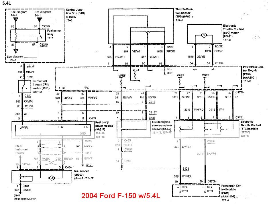
Updated with factory electrical diagram and modified setup. I'm hosting through a host I haven't used before(work allows me to upload to this site and not photobucket or imageshack).
I still need to modify the one I made with a little more detail later this week. Also noticed an error that my pump #1 and #2 need to be reversed.
I still need to modify the one I made with a little more detail later this week. Also noticed an error that my pump #1 and #2 need to be reversed.
Last edited by FATHERFORD; Aug 16, 2010 at 09:36 AM.


Senior Member
Joined: Jun 2008
Posts: 557
Likes: 0
From: Durham, NC
so FF,
what made you upgrade from the setup you had to this new setup? Were you on the border line with the GT pump and boost-a-pump and needed more for peace of mind or is it for future mods needing the increase in fuel? I have the GT fuel pump and boost a pump setup myself and was just curious...thanks
what made you upgrade from the setup you had to this new setup? Were you on the border line with the GT pump and boost-a-pump and needed more for peace of mind or is it for future mods needing the increase in fuel? I have the GT fuel pump and boost a pump setup myself and was just curious...thanks
Last edited by batn68; Aug 20, 2010 at 01:16 PM. Reason: corrected some wording
so FF,
what made you upgrade from the setup you had to this new setup? Were you on the border line with the GT pump and boost-a-pump and needed more for ease of mind or is it for future mods needing the increase in fuel? I have the GT fuel pump and boost a pump setup myself and was just curious...thanks
what made you upgrade from the setup you had to this new setup? Were you on the border line with the GT pump and boost-a-pump and needed more for ease of mind or is it for future mods needing the increase in fuel? I have the GT fuel pump and boost a pump setup myself and was just curious...thanks

Senior Member
Joined: May 2007
Posts: 257
Likes: 0
hey father ford im about to install the force fule system on my truck and i need a lil help.
i got 2 questions on the relays their is 3 red wires is the 3rd one just in case i were to use 3 fule pumps? and second how do i take of the original pilow filter and the white plastic around the fule pump so i can slide it in the fule hat hole? i called troyer and they
told me they dont send the fule kit with instructiuons lol so if it wasent for this awesome write up u did i would be stuck in sh*t.
Senior Member
Joined: May 2007
Posts: 257
Likes: 0
thanks alot fatherford,i finally figured out how to take of the original pillow filter were the pump sucks in the fule.maybe they sent u ur fule pumps ready to just slide in he force fule hat,but mine were still stock locking like to replace an original ford gt fule pump so i had to take of the stock pillow filter in the bottm of fule pump and a whithe plastic that was arount the fule pump so it could fit in the force fule hat hole and also take off the original hose on top of the fule pump that would originaly conect to the ford gt fule hat i took that off and now just slide it in the force fule hat and use the supplied hose clamps to secure it in place. thanks again for the info can u pm me some info on ur rear suspension thanks again.
I've seen them before.