How-To: Build and Install your own Line Lock **PICS**


Thread Starter
|
Technical Article Contributor
Joined: Jan 2006
Posts: 1,292
Likes: 0
From: Port Royal, SC
How-To: Build and Install your own Line Lock **PICS**
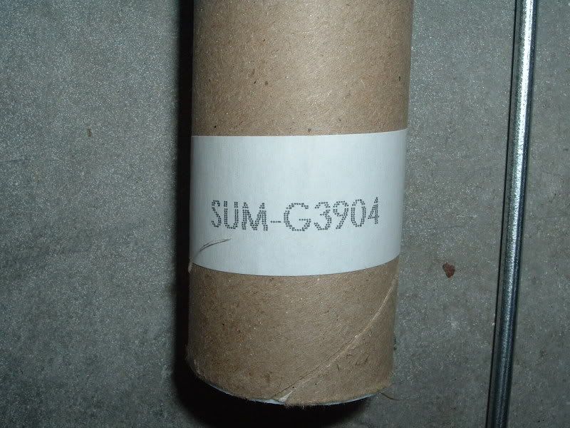
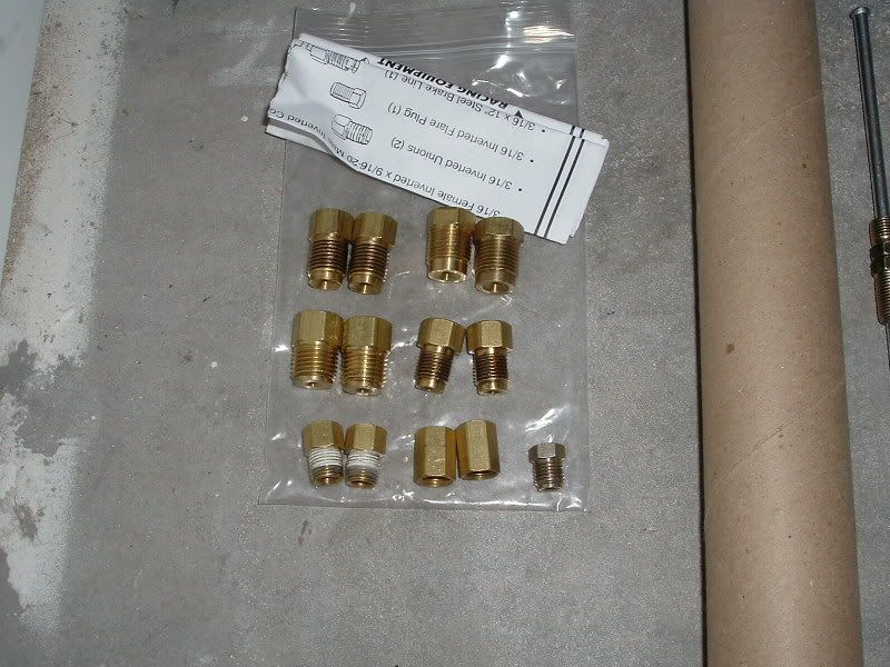
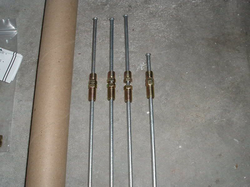
I just got done installing my line lock. I bought a used PSP Line Lock Kit from another member a while ago and when I went to install it a couple weeks ago the hard line leaked. It leaked at the fitting on the solenoid and no matter what I did I couldn't get it to stop. I suspect there was a problem with the flared end of the line mating with the inside of the fitting. So I decided to just scrap all the stuff that came with the kit and just use the solenoid to build my own kit. I ended up buying the Summit Line Lock Installation Kit (Part# SUM-G3904). It comes with 4 hard lines that are already flared and have fittings on them. It also comes with an assortment of fittings. Some for the solenoid and some to adapt the hard lines to the brake system. I also bought a rocker switch with an LED on it from my local Advanced Auto and while and while I was there I also picked-up an Add-a-Fuse to tap into the fuse panel for the power supply. All of the other stuff I used I already had. I used two different tubing benders, some 14 gauge wire and a few connectors. All of which will be pictured later in this thread. Here's a few pics of some of the stuff I used...
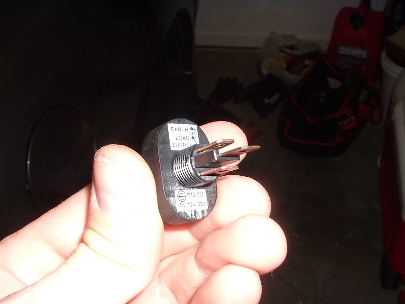
This is the Line Lock that came with the PSP Kit. I removed the sticker but it's a Hurst Solenoid (Part# HUU-1745000) and can be purchased from Summit along with the Install Kit...
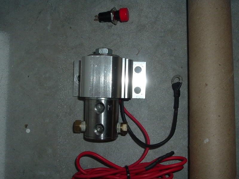
This is the Line Lock that came with the PSP Kit. I removed the sticker but it's a Hurst Solenoid (Part# HUU-1745000) and can be purchased from Summit along with the Install Kit...
Thread Starter
|
Technical Article Contributor
Joined: Jan 2006
Posts: 1,292
Likes: 0
From: Port Royal, SC
I decided to mount my solenoid in a different spot than most mount theirs. I mounted mine on the firewall underneath the brake booster. It makes for a clean install and keeps the clutter in the engine bay down. First I had to remove the drivers side front tire and the wheel well splash shield. I jacked up that corner and used a jackstand to ensure safety. Removing the tire is obvious and removing the splash shield is as simple as removing 4 screws and a few push pins...
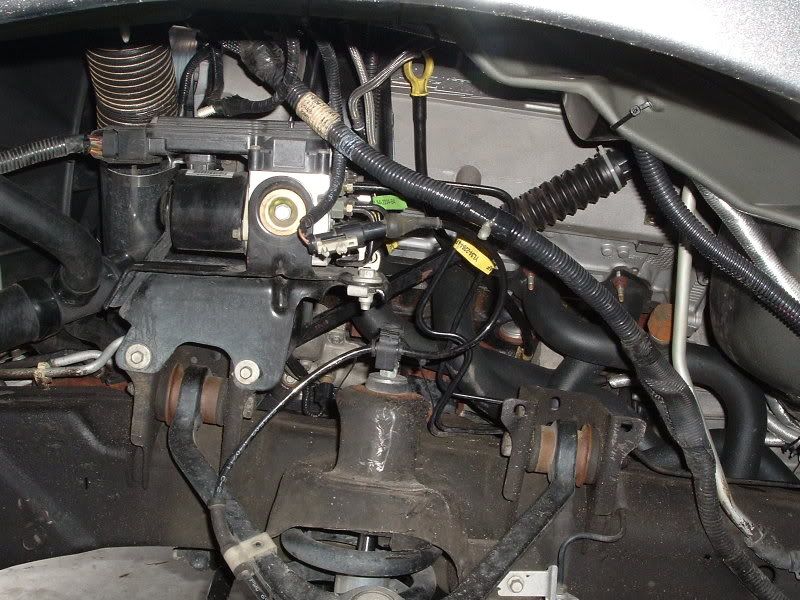
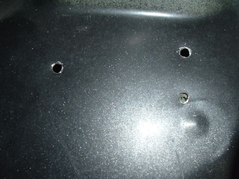
This gave me access to the components of the brake system I needed to modify and the location I chose to mount my line lock solenoid. Next I needed to mark where to drill the holes for the solenoid. I had previously removed the plate bracket that came on the solenoid from PSP. This leaves 3 holes to drill and here is how I marked and drilled them...
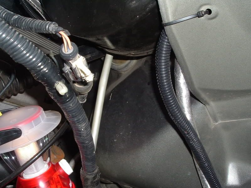
This gave me access to the components of the brake system I needed to modify and the location I chose to mount my line lock solenoid. Next I needed to mark where to drill the holes for the solenoid. I had previously removed the plate bracket that came on the solenoid from PSP. This leaves 3 holes to drill and here is how I marked and drilled them...
Thread Starter
|
Technical Article Contributor
Joined: Jan 2006
Posts: 1,292
Likes: 0
From: Port Royal, SC
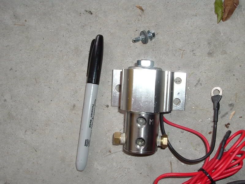
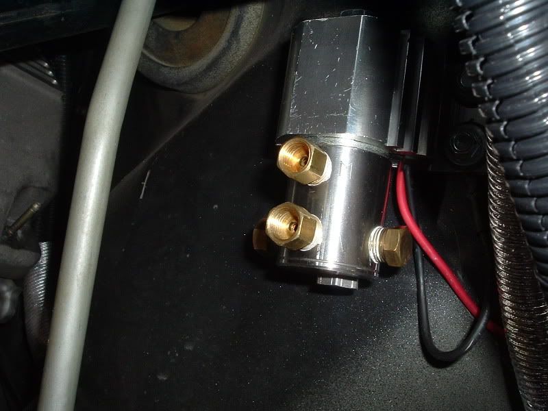
Then I mounted the solenoid using 3 self-tapping screws...
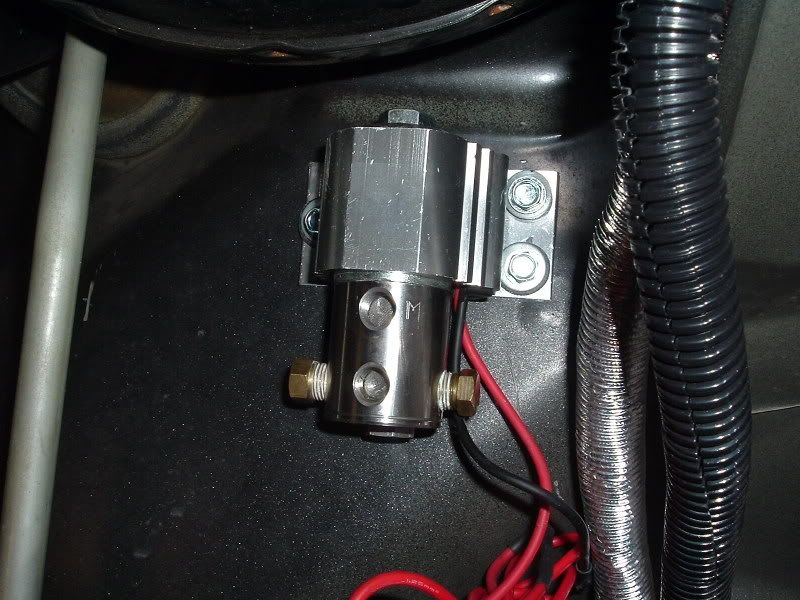
I took this opportunity to go ahead and ground the solenoid. I just grounded the wire between the solenoid and the firewall and secured it with one of the screws I used to mount the solenoid...
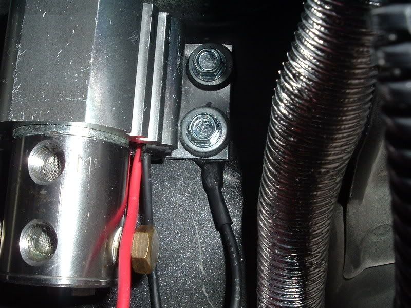
I had already extended the positive wire from the solenoid previously. I'll cover how to make a good connection later...
Thread Starter
|
Technical Article Contributor
Joined: Jan 2006
Posts: 1,292
Likes: 0
From: Port Royal, SC
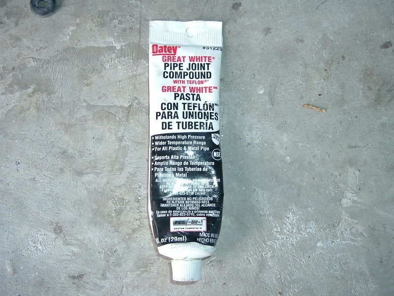
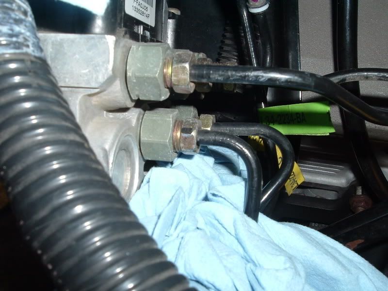
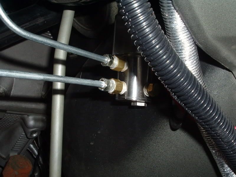
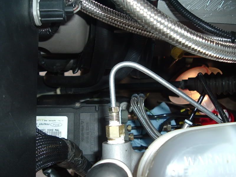
Next I installed the solenoid fittings. I used a little pipe joint compound I already had to ensure a good seal. This particular compound can be purchased at Lowes. A 7/16 wrench is required...
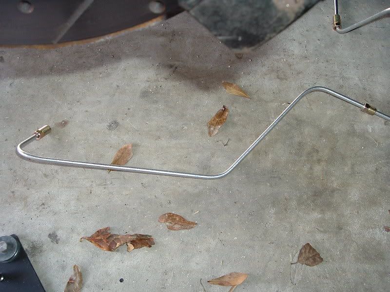
Then I installed the shortest of the 4 hard lines to see what kind of bends I needed to make. I used this hard line to connect the the lower fitting on the solenoid to the ABS fitting...
Then I installed the shortest of the 4 hard lines to see what kind of bends I needed to make. I used this hard line to connect the the lower fitting on the solenoid to the ABS fitting...
Thread Starter
|
Technical Article Contributor
Joined: Jan 2006
Posts: 1,292
Likes: 0
From: Port Royal, SC
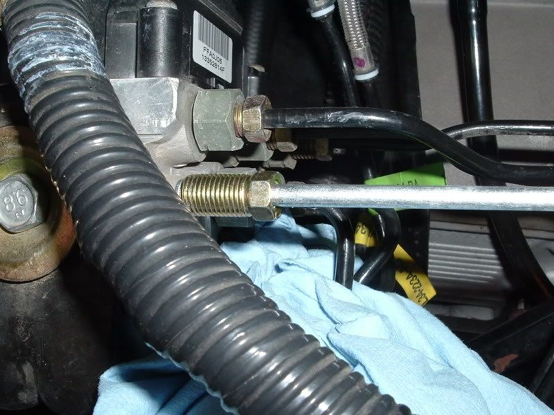
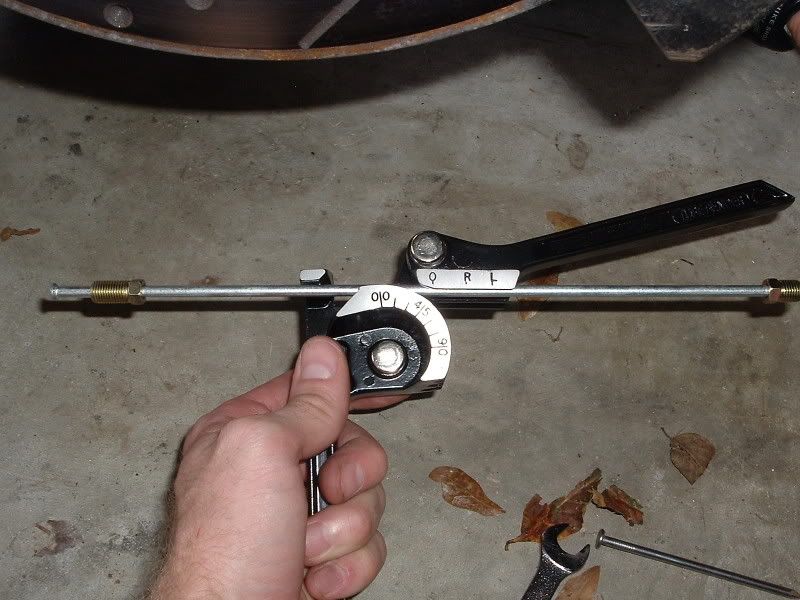
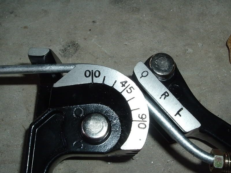
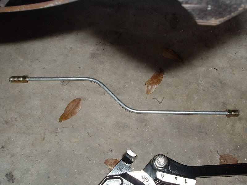
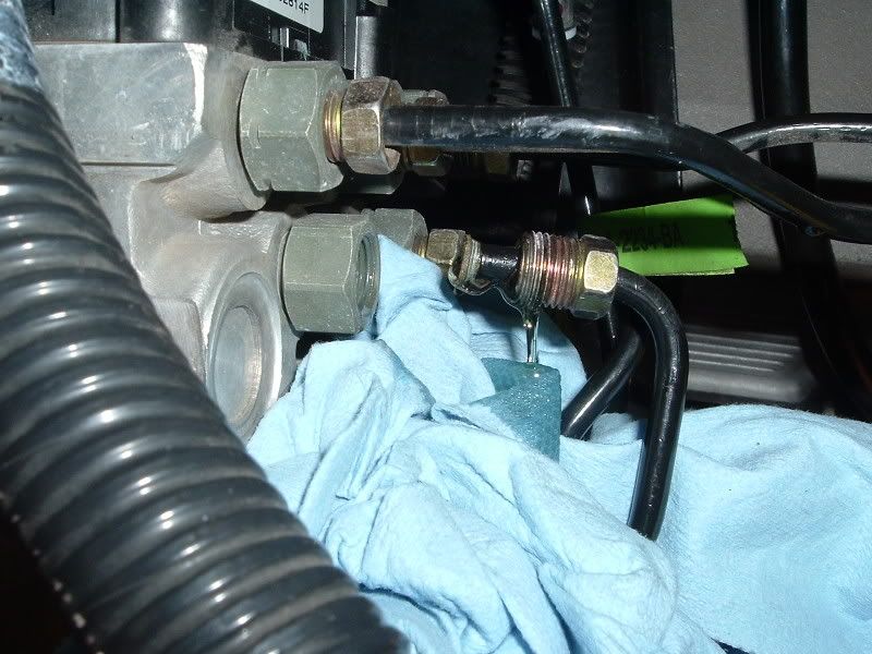
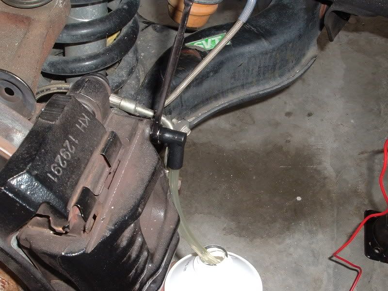
It was sitting dead even with the ABS fitting (lower left hand corner of the ABS block) but I needed to make some bends to get it to fit. The tubing bender I used I purchased from Lowes and it was pretty cheap. I can;t remember the cost as I've had it for about a year. All I had to do to make the tube line up perfect was make 2 45 degree bends....
Next I had to disconnect the stock line from the ABS block. I used a 7/16 wrench to do so. Make sure to place some rags underneath the fitting as you will lose a little fluid once it's removed...
Next I had to disconnect the stock line from the ABS block. I used a 7/16 wrench to do so. Make sure to place some rags underneath the fitting as you will lose a little fluid once it's removed...
Thread Starter
|
Technical Article Contributor
Joined: Jan 2006
Posts: 1,292
Likes: 0
From: Port Royal, SC
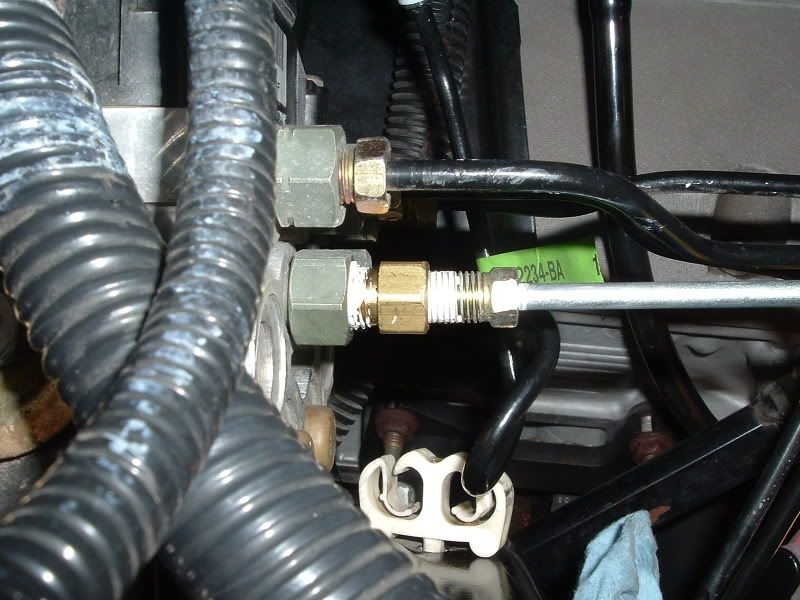
Then I applied some pipe thread compound to one of the fittings that came with the kit and installed it. A 13mm wrench is required to install the new fitting...
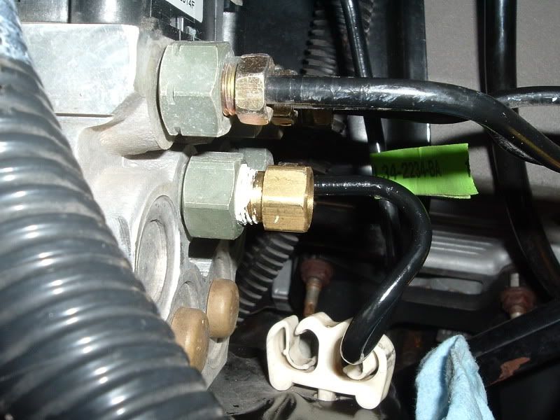
Then I installed the line I just got done bending. A 10mm wrench is required to install the hard line fittings at the ABS block and the lower fitting of the solenoid. I went ahead and applied some pipe thread compound to these fittings even though I didn't really have to...
Thread Starter
|
Technical Article Contributor
Joined: Jan 2006
Posts: 1,292
Likes: 0
From: Port Royal, SC
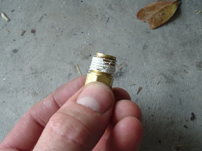
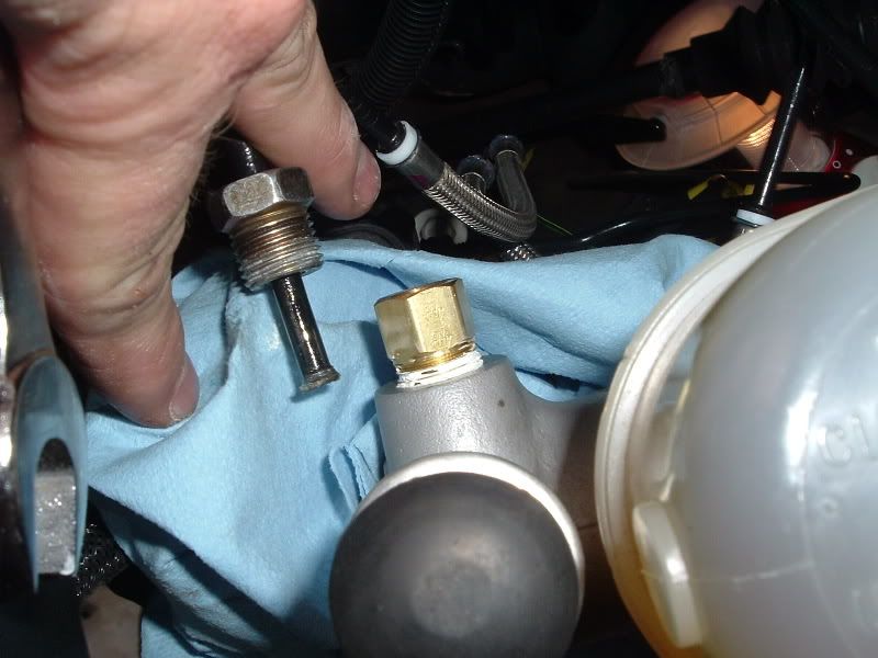
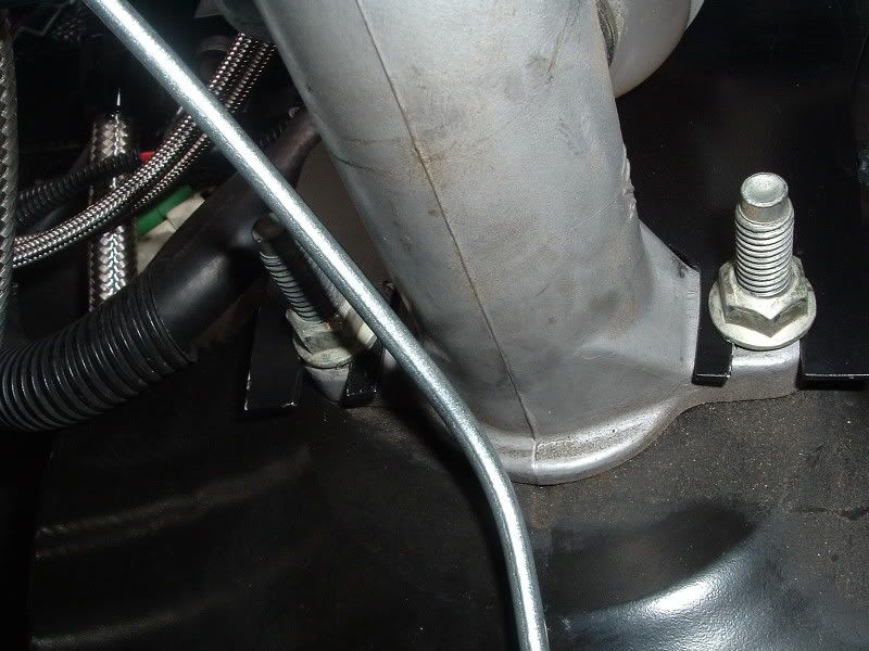
Then I had to remove the fitting from the master cylinder. The correct fitting is the one located in the front portion of the master cylinder as shown in the picture below. This fitting requires a 5/8 wrench to remove...

The I applied some pipe thread compound to one of the fittings that came in the kit and installed it into to master cylinder. A 9/16 wrench is required to install this fitting...
Trending Topics
Thread Starter
|
Technical Article Contributor
Joined: Jan 2006
Posts: 1,292
Likes: 0
From: Port Royal, SC
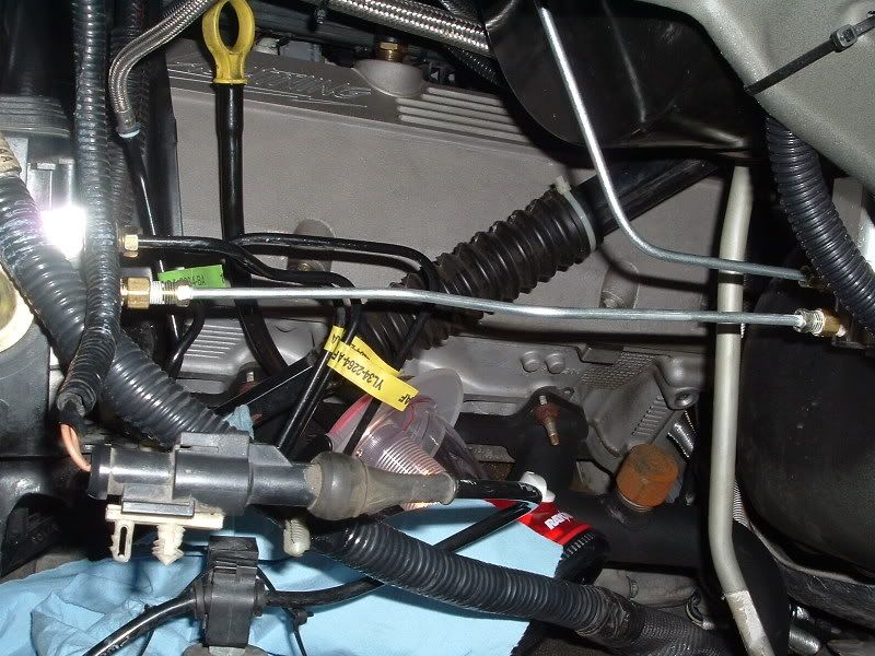
At this time I went ahead and removed the factory line as it was no longer needed...
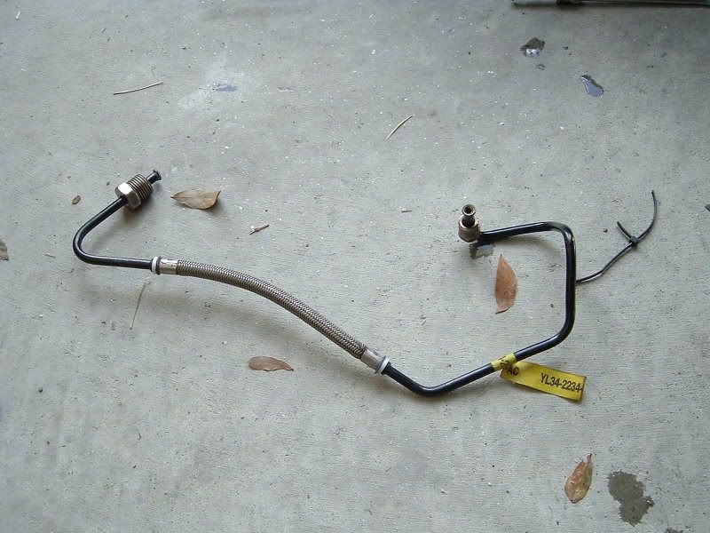
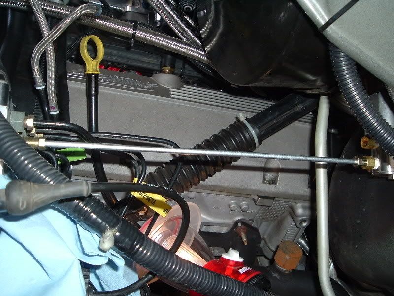
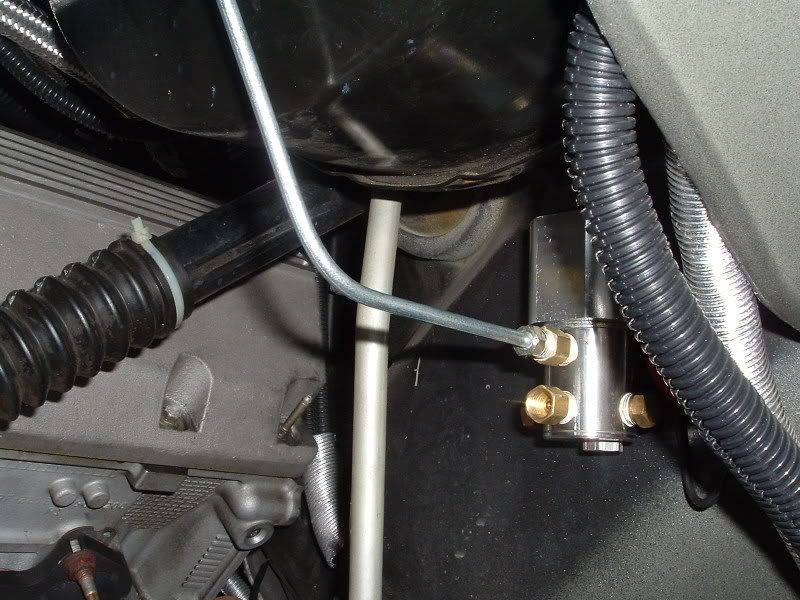
Then I had to bend a hard line to connect the master cylinder to the top fitting on the solenoid. I used the tubing bender shown earlier and also had to use my NOS tubing bender for one of the bends. I purchased the NOS tubing bender from Nitrous Outlet, Complete Nitrous Kits & Nitrous Accessories and it is part# NOS-15991. This tubing bender is great for tighter radius bends...
Thread Starter
|
Technical Article Contributor
Joined: Jan 2006
Posts: 1,292
Likes: 0
From: Port Royal, SC
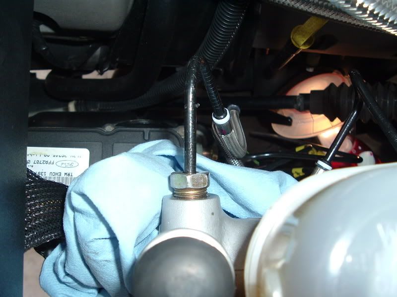
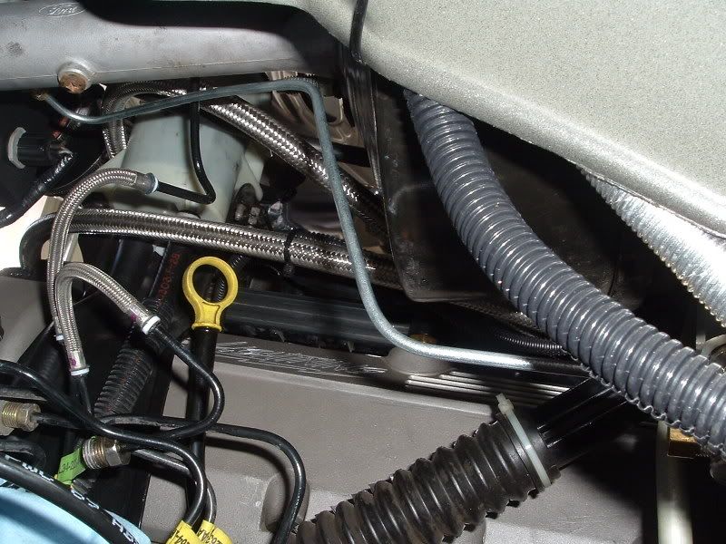
It took a little trial and error to get the tube just right but in the end it fit great. I bent the tube to follow the contour of the brake booster and then underneath the master cylinder. It then comes out and makes a tight bend into the master cylinder. I went ahead and applied some pipe thread compound and installed the line. A 10mm wrench is required for the fittings on the line...
Thread Starter
|
Technical Article Contributor
Joined: Jan 2006
Posts: 1,292
Likes: 0
From: Port Royal, SC
At this point it was time to bleed the brakes and check for leaks. I did and there were none. A 3/8 wrench is required for the bleeder screws to bleed the brakes. It has been said that you only need to bleed the front brakes. That may be but I would feel a lot better bleeding all 4 corners. Remember to bleed them in this order: Passenger side rear, drivers side rear, passenger side front and drivers side front...
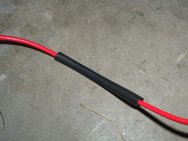
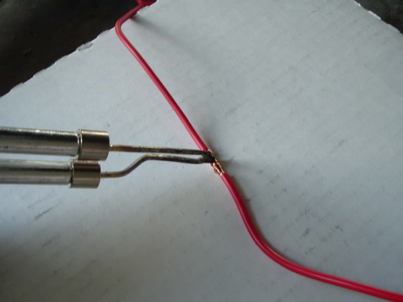
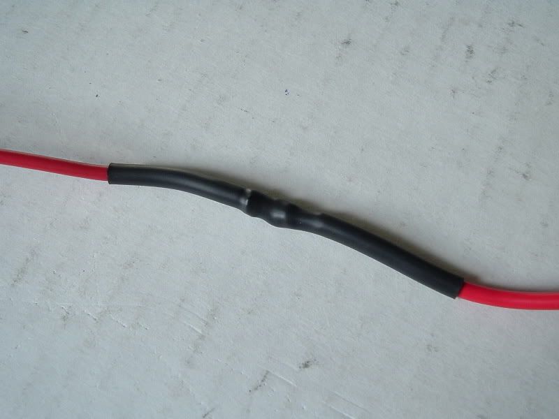
Below is an illustration of how I extended the positive wire from the solenoid. This is also how I soldered all of the connections for this install. First I slid some heat-shrink onto the wire...
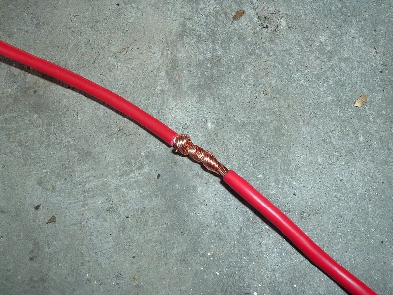
Then I stripped the insulation off both ends that were to be connected and wrapped them around each other...
Thread Starter
|
Technical Article Contributor
Joined: Jan 2006
Posts: 1,292
Likes: 0
From: Port Royal, SC
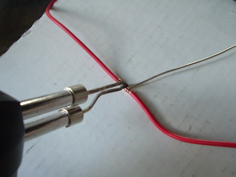
Then I placed the tip of my soldering iron on the twist and squeezed the trigger to allow the wire to get nice and hot before applying solder...
Then I applied some rosin core solder. You know a good soldering connection is made when the solder wicks itself into the wires...
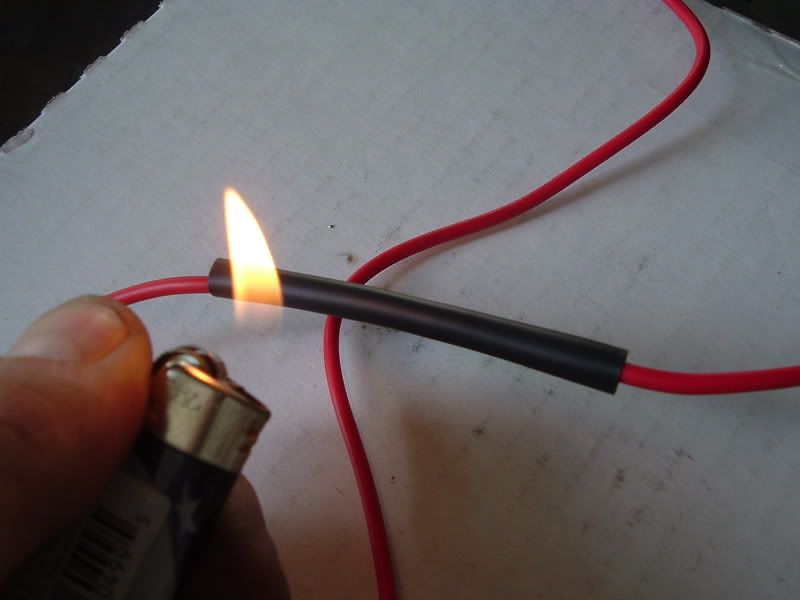
Then I slid the heat-shrink over the connection and applied heat with a lighter...
Then I applied some rosin core solder. You know a good soldering connection is made when the solder wicks itself into the wires...
Then I slid the heat-shrink over the connection and applied heat with a lighter...
Thread Starter
|
Technical Article Contributor
Joined: Jan 2006
Posts: 1,292
Likes: 0
From: Port Royal, SC
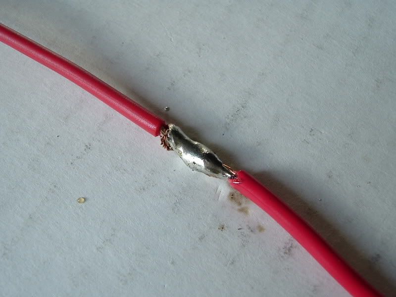
And here is the end result...
Next I put some black split loom on the positive wire and wrapped some electrical tape around one end. I purchased the split loom and the tape from NAPA...
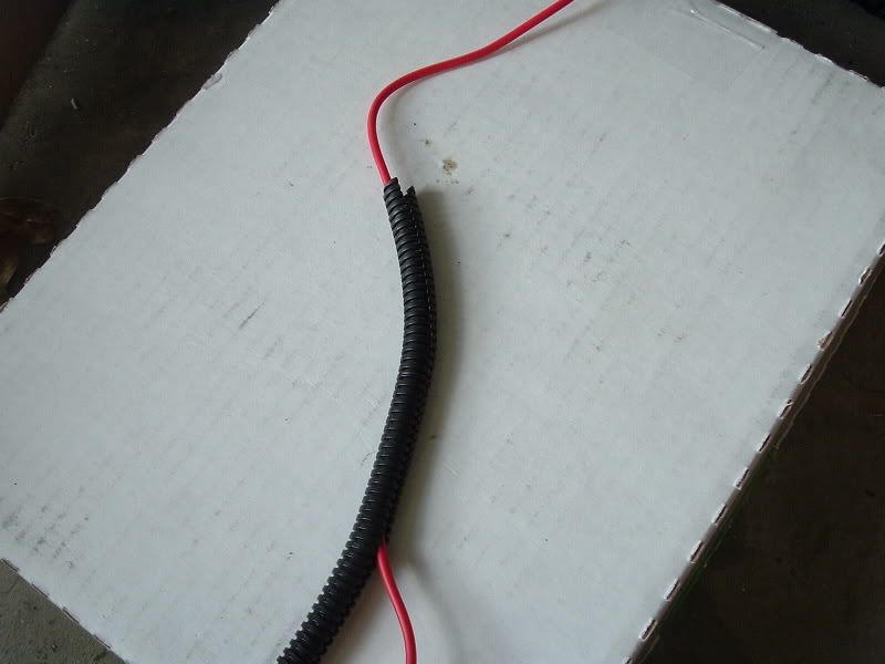
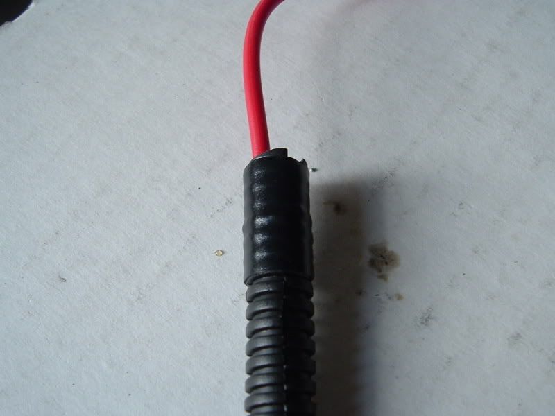
Then I pushed it up all the way to the solenoid...
Next I put some black split loom on the positive wire and wrapped some electrical tape around one end. I purchased the split loom and the tape from NAPA...
Then I pushed it up all the way to the solenoid...
Thread Starter
|
Technical Article Contributor
Joined: Jan 2006
Posts: 1,292
Likes: 0
From: Port Royal, SC
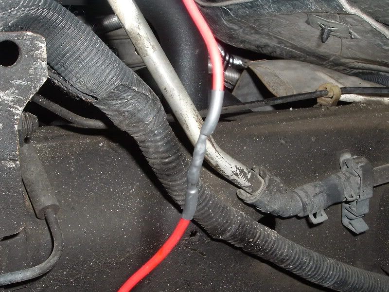
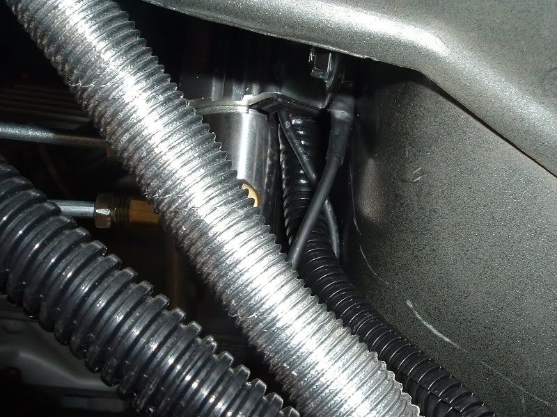
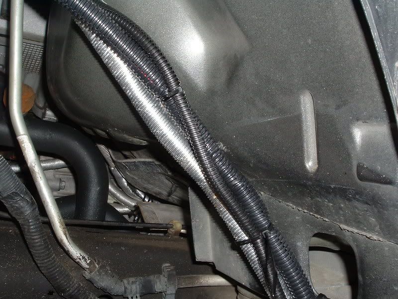
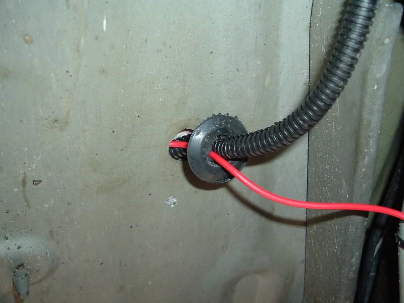
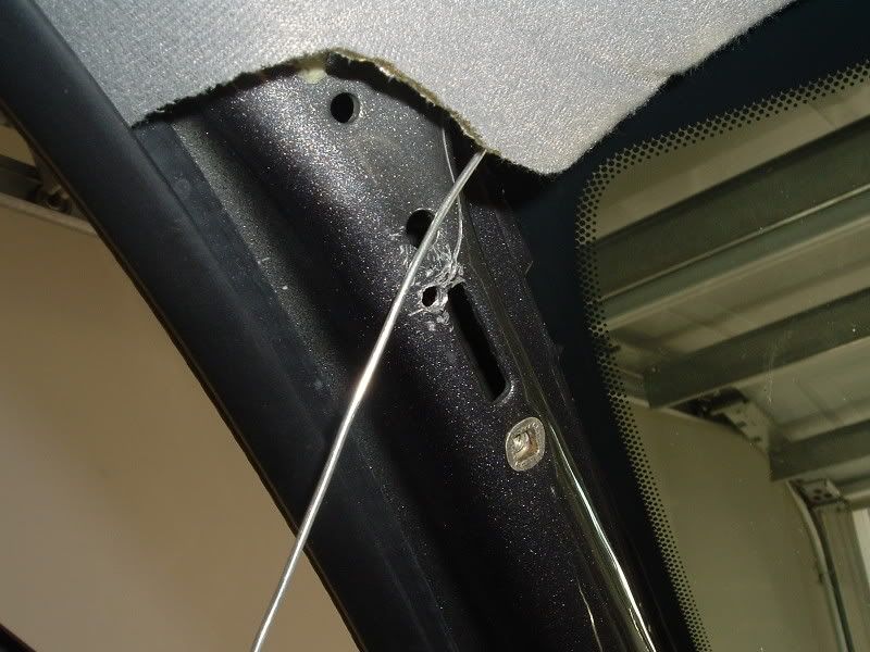
Then I ran the wire along some existing wires and tie wrapped it to them. I could have run this wire through the grommet in the firewall where the boost line comes through. But that grommet was already full with all my nitrous system wires. So I decided to enter the cab through one of the grommets in the floor pan right enderneath where your feet go...
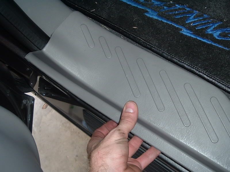
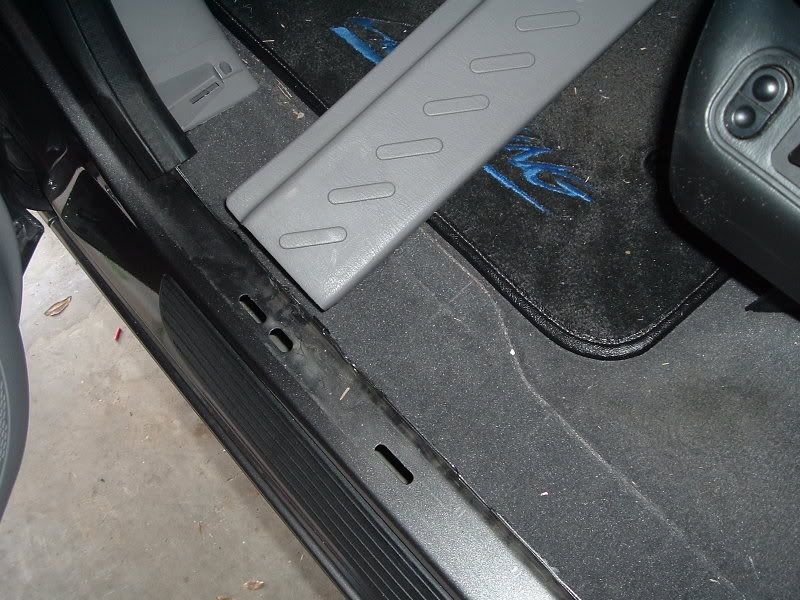
I opened the drivers side door and removed the panel pictured. Just pull on it and it will snap loose. Then I lifted the carpet which allowed me access to the top of the grommet I was using...
I opened the drivers side door and removed the panel pictured. Just pull on it and it will snap loose. Then I lifted the carpet which allowed me access to the top of the grommet I was using...
Thread Starter
|
Technical Article Contributor
Joined: Jan 2006
Posts: 1,292
Likes: 0
From: Port Royal, SC
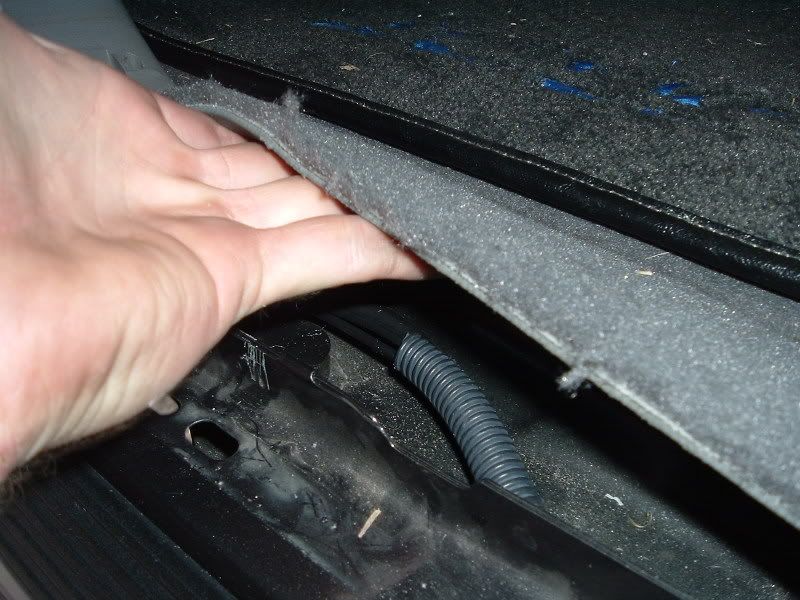
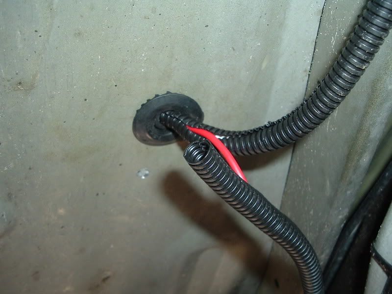
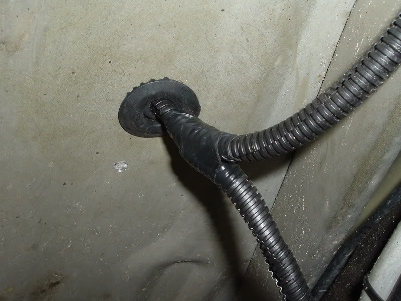
Then I ran the wire through the grommet. Don't mind the wire that's already going through it. That goes to something else. Just make a hole in the grommet with a screwdriver and run the wire through...
I intersected the wire with the split loom that was already going through and used electrical tape to seal them together. This grommet is pretty soft and the split loom can be pulled through very easily...
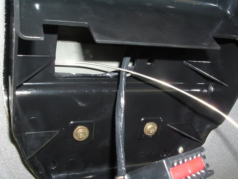
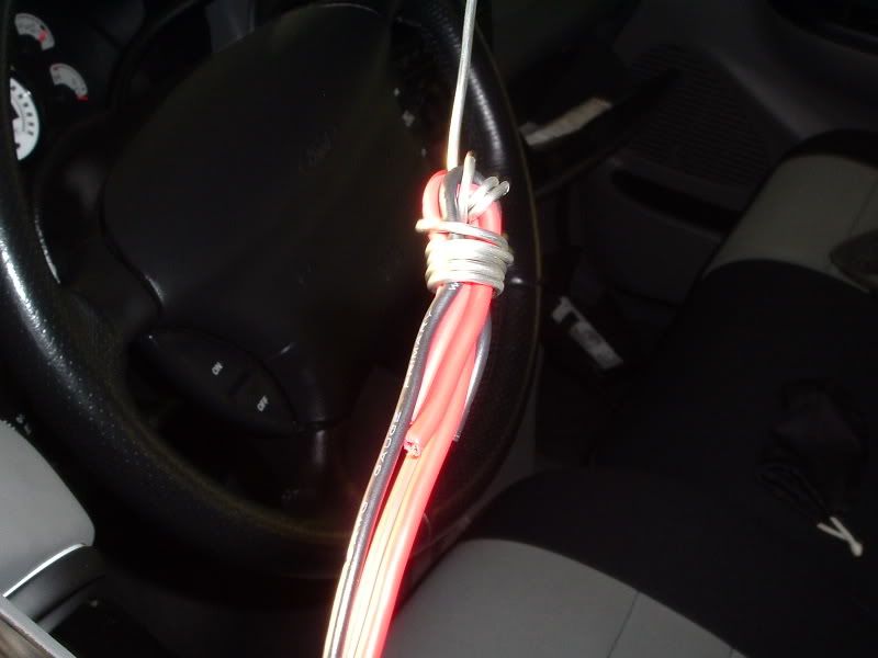
Next I had to find a suitable location to mount the switch. I looked all aver and it took me a good hour to decide on a location. I decided to mount it in the sunglasses holder in the overhead console. This may be a little much for some people so if you decided to mount your switch in a different location the wiring will still be the same. I had to remove the console which was very easy. There is a phillips head screw in the very front that needs to be removed and then just pull on the console and it will snap loose. There is a connector that needs to be disconnected that supplies power to the console display. After that, I just set the console aside. I had to get the solenoid wire, power wire, and switch ground wire over to the console from the pillar but didn't want to remove the headliner or the visor. So I just fed some of my soldering wire from the opening in the console over to the pillar...
I intersected the wire with the split loom that was already going through and used electrical tape to seal them together. This grommet is pretty soft and the split loom can be pulled through very easily...
Next I had to find a suitable location to mount the switch. I looked all aver and it took me a good hour to decide on a location. I decided to mount it in the sunglasses holder in the overhead console. This may be a little much for some people so if you decided to mount your switch in a different location the wiring will still be the same. I had to remove the console which was very easy. There is a phillips head screw in the very front that needs to be removed and then just pull on the console and it will snap loose. There is a connector that needs to be disconnected that supplies power to the console display. After that, I just set the console aside. I had to get the solenoid wire, power wire, and switch ground wire over to the console from the pillar but didn't want to remove the headliner or the visor. So I just fed some of my soldering wire from the opening in the console over to the pillar...
Thread Starter
|
Technical Article Contributor
Joined: Jan 2006
Posts: 1,292
Likes: 0
From: Port Royal, SC
Then I wrapped the soldering wire around the 3 wires and pulled them through...
At this time I went ahead and installed the connectors that would allow me to connect the wires to the switch. I removed the insulation on the connectors because I was going to solder them and add heat-shrink tubing...