


new E-fans installed


Thread Starter
|
Member
Joined: Dec 2005
Posts: 34
Likes: 0
From: Milo, Missiuri
new E-fans installed
I just installed a pair of Zirgo 16" E-fans on my 02 Screw. I had read where some one had taped into the over drive wire for turning the fans off at hwy speeds. what I was needing to know is where the wire is located. Right now i have it set up with the temp switch going to one relay for one fan. and one more relay getting turned on from the A/C unit. I wanted to add that I had read that the A/C wire to use was blk with green stripe, but on my 02 it was gray with white stripe. if this helps anyone. Every thing went good with the install and I went from low 14's mpg to mid 16's mpg on the hwy with the A/C on. I haven't reclaed the speedo after i installed my 285's so the mpg should be higher. But any help on the over drive wire would be great.

Senior Member
Joined: Feb 2007
Posts: 707
Likes: 0
From: Houston, TX
I put a FlexALite 270 on my truck. I never put in the AC wire. I am in Houston and honestly I only turned on the manual on switch for the AC a couple times for the week I have had them on now.
I asked in the forum here and one reply had a good point regarding the AC on at highways speeds. He explained that once you have a good flow from a decent speed the fans being on can eventually stress them out and cause premature failure. I run all the time with the AC on here (spring to mid fall).
I understand your setting the overdire but why not just use a manual switch instead of changing the tranny setting as well. I was going to wire a manual off since the unit has the ability to do so but I was lazy. I just wired the manual on and used it only a couple times when watching the Evolution gauge when adjusting the controller settings. I hit it once when waiting i a drive through for AC only.
I found even at 30 MPH there is enough airflow that the fans don't even turn on. Well at least not that I notice since the FAL controller has a stepped speed on the fans. They are not ON-OFF, they go insteps. I guess I should wire up the LED also to watch when the fans are engaged. I can usually tell by watching the Evo gauge.
I asked in the forum here and one reply had a good point regarding the AC on at highways speeds. He explained that once you have a good flow from a decent speed the fans being on can eventually stress them out and cause premature failure. I run all the time with the AC on here (spring to mid fall).
I understand your setting the overdire but why not just use a manual switch instead of changing the tranny setting as well. I was going to wire a manual off since the unit has the ability to do so but I was lazy. I just wired the manual on and used it only a couple times when watching the Evolution gauge when adjusting the controller settings. I hit it once when waiting i a drive through for AC only.
I found even at 30 MPH there is enough airflow that the fans don't even turn on. Well at least not that I notice since the FAL controller has a stepped speed on the fans. They are not ON-OFF, they go insteps. I guess I should wire up the LED also to watch when the fans are engaged. I can usually tell by watching the Evo gauge.
Thread Starter
|
Member
Joined: Dec 2005
Posts: 34
Likes: 0
From: Milo, Missiuri
I had thought about putting in a manual switch when i was doing it but it was getting late and i had to get it going. I might just hook both fans up to the temp switch and put the manual switch in the cab and add one more relay. Just have to make sure that the switch is on when i park it so my wife don't get in it and forget to turn them on.

Senior Member
Joined: Aug 2006
Posts: 1,274
Likes: 6
From: Simi Valley CA
I am getting ready to install my FAL 270 and had the same concerns. I did find a box in the engine compartment that has the connections that I think would work. The box in question is the Auxiliary Relay box fround on page 199 of the 2004 owner guide. I am posting these pictures in hopes that someone who has an electrical manual or has used this method before will be able to verify that this would be a good place to tap into for the FAL electrical signals.
The red wire with the yellow stripe in the top left corner of the picture has power when ever the ignition is on.
The Grey and white (looks white) wire in the middle is on when ever the AC clutch is engaged.

Here is a picture of the box which has been removed from the drivers side fender well and has the bottom plastic cover removed.

The red wire with the yellow stripe in the top left corner of the picture has power when ever the ignition is on.
The Grey and white (looks white) wire in the middle is on when ever the AC clutch is engaged.
Here is a picture of the box which has been removed from the drivers side fender well and has the bottom plastic cover removed.
Senior Member
Joined: Aug 2006
Posts: 1,274
Likes: 6
From: Simi Valley CA
Originally Posted by LightningNoMore
so in that box does it have the right pin lay out for a relay or were you going to use jumpers to run a remote relay
Last edited by MeanGene; Jul 9, 2007 at 07:25 PM.
Trending Topics
Thread Starter
|
Member
Joined: Dec 2005
Posts: 34
Likes: 0
From: Milo, Missiuri
Originally Posted by MeanGene
The Flex-a-lite kit comes with its own relay or more accurately a controller; all you need to do it connect it to your battery to power the fans. The controller signals the fans to come on and at what speed depending on the temperature of the radiator. The FAL controller does need to have some additional connections, one connection to sense when the power is on and one to know when the AC is on. Because the instructions were written for pre 3v trucks which have the main fuse box in the engine bay and not in the cab like our 2004 and up trucks, were on our own in finding the best place to tap into those sources that will give the FAL controller the information it needs to work properly. Does that make sense now?

Technical Article Contributor
Joined: Jun 2002
Posts: 10,511
Likes: 10
From: Under the flightpath of old ORD 22R
Originally Posted by MeanGene
..<snip>..I did find a box in the engine compartment that has the connections that I think would work...<snip>...
The red wire with the yellow stripe in the top left corner of the picture has power when ever the ignition is on.
The Grey and white (looks white) wire in the middle is on when ever the AC clutch is engaged...<snip>..
The red wire with the yellow stripe in the top left corner of the picture has power when ever the ignition is on.
The Grey and white (looks white) wire in the middle is on when ever the AC clutch is engaged...<snip>..
2. Do you have DRLs ?
The box looks to be for a 4x2 without DRLs, but I can't be 100% sure, but this is what I am going to work from :
There is an A/C clutch Relay, and the fuse for the clock spring illumination.
This is what it looks to be this from the amount of wiring on the back side, again just a guess right now.
Working from the 2006 EVTM ( should be the same, but verify ) :
Clock spring illumination :
To F1 in the AUX relay box Light Blue w/ Red Stripe
Circuit 19 fed from the Main headlamp switch, pin #1
From F1 to the clock spring Illumination Tan w/ Orange stripe.
A/C Relay ( EATC ):
Pin 1 : ( one side of coil ) Pink w/ Light Blue stripe is fed from Fuse F32.
This is the PCM Power Relay, fed from a hot at all times circuit on F11.
When the PCM is active, the ground on the PCM Power Relay coil is completed, and F11 feds F32.
Pin 2 : ( One side of coil ) Pink w/ Yellow Stripe.
This is fed from the PCM pin #18 Should be a ground signal, to close the coil on the A/C Clutch Relay
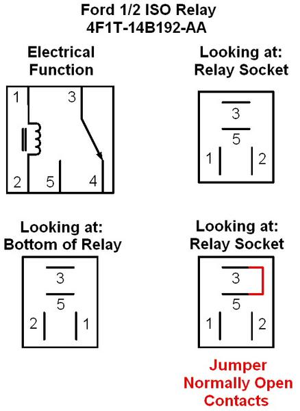
Pin 3 : ( one side of N.O. Contacts ) Pink w/ Light Blue Stripe Circuit 883. Same circuit from F11 above, Hot at all times.
Pin 5 : ( one side of N.O. Contacts ) Gray w/ White Stripe.
When PCM completes coil circuit, the contacts close, and pin #3 on the relay is connected to Pin #5. This is what supplies power to the A/C Clutch Solenoid. Other side of Solenoid is Black, circuit # 57.
A/C Compressor Clutch Diode is connected from ground to Circuit on Pin #5.
So you are correct, the +12 V side of the coil ( Pink w/ Light Blue stripe ) is only hot when the PCM is active, so that would be a good Run enable circuit for the FAL controller ( think that is what it was called...been a while ).
The enable pin for 60% run with the A/C would be pin #5, Gray w/ White stripe wire.
Side Note : For those wanting to use the holder, the Open Full size ISO relay slot ( 4x2 or 4x4 without DRL ) would be the same size as a standard Bosch type Auto Relay. Trip to the bone yard to get the pins, and the relay could be hung in the open slot. The pins are not there when the item is not installed ( look at the bottom picture above ).
Reference Material :
Relay Pin out Ford 1/2 size ISO :
Relay Bosch Automotive type relay :
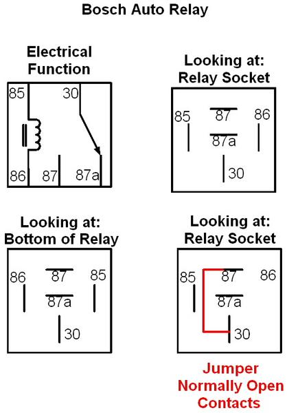
Full size ISO relay from ford, same pin assignments for functions ( coil, common and N.O. / N.C. Contacts ) on Ford Full size for A/C Relay.
Good luck, hope this helps !

Global Moderator &
Senior Member
Senior Member

Joined: Aug 2005
Posts: 21,337
Likes: 159
From: DFW
I have only one fan so far, and it never turns on when driving down the highway, b.c there is enough air going over the radiator. Im gonna just wire a manual switch for the AC fan once i get it. after about 30mph the fan is useless, and you can actually start eating up the fan motor by trying to spin it faster then it can turn.
-Patrick
-Patrick
Senior Member
Joined: Aug 2006
Posts: 1,274
Likes: 6
From: Simi Valley CA
Did anyone every discover the wire that could be used to turn off the fan controller when in over-drive? My AC is always on and I am wondering if the fans will be running at highway speeds or will the air coming in cause the temp sensor to shut the fans down even with the AC on? Maybe it's not really a problem.

Senior Member
Joined: Jun 2007
Posts: 136
Likes: 0
From: Alberta, Canada
Im in the process of installing the flex a lite controller and i just need to find out a good place to splice into for the AC signal. A picture would be perfect. Other than that i have everything up and running, right now im just not using the ac until i find which wire to hook it up to. Heres a pic of my setup, just did it today.


Senior Member
Joined: Aug 2006
Posts: 1,274
Likes: 6
From: Simi Valley CA
Originally Posted by RdHammer
Im in the process of installing the flex a lite controller and i just need to find out a good place to splice into for the AC signal. A picture would be perfect. Other than that i have everything up and running, right now im just not using the ac until i find which wire to hook it up to. Heres a pic of my setup, just did it today.
Did you read this whole thread? I think you answer is up a couple of posts.

Senior Member
Joined: Aug 2006
Posts: 1,224
Likes: 0
From: Summerville, SC
havn't quite seemed to get an answer from this thread. not one that i can understand anyway.
i want to know what to wire into to get the fans to turn off at highway speed. only thing im concerned about.
i want to know what to wire into to get the fans to turn off at highway speed. only thing im concerned about.

