


fog lamps & Relay


Thread Starter
|
Junior Member
Joined: Feb 2004
Posts: 5
Likes: 0
fog lamps & Relay
I bought some aftermarket fog lamps (cause I didnt have any to begin with) and I have them all wired up, I purchased a relay w/ the hopes I wouldnt have a CarBBQ later down the road, I guess Im not smart enough to figure out how to wire it up. I have the 3 wires from the wiring kit, ground, fused power and switching wires.
I have the relay which is some HD 12volt deally I got at checker auto, I cant figure out how to wire it to the switch.
The switch has power, ground, feed from the lights.
The relay has fused power peg, ground peg, 2 lamp feed pegs & an out to switch peg. Does this mean I need to make Y-harnesses for the other 2 pegs on my switch or should I just take it to someone who knows better. It shouldnt be this hard, I built a tranny but can't do this little task
 even with instructions...
I have the relay which is some HD 12volt deally I got at checker auto, I cant figure out how to wire it to the switch.
The switch has power, ground, feed from the lights.
The relay has fused power peg, ground peg, 2 lamp feed pegs & an out to switch peg. Does this mean I need to make Y-harnesses for the other 2 pegs on my switch or should I just take it to someone who knows better. It shouldnt be this hard, I built a tranny but can't do this little task
even with instructions...

Technical Article Contributor
Joined: Jun 2002
Posts: 10,511
Likes: 10
From: Under the flightpath of old ORD 22R
Take look at these :
Basic AUX lamp install showing what some options are for an install

Note what I took to the be the question about the Y in the harness, being for the power to the aux lamps themselves ( in the lower right hand quadrant of the drawing )
a switch to turn them on and off independent of the power source would be installed between the input options ( A or B or C ) and the terminal #85 on the relay.
Note the fuse near the battery ( closer the better ) for the supply to the aux lamps ( between the battery + terminal and pin #30 )
This is a close up of the relay that I think you have :
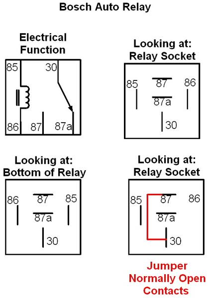
The jumper part IGNORE. This is for trouble shooting work, not applicable for normal installed ( and it is looking into a relay socket ).
It might not be the cube version, but the pin assignments should still be the same.
Let us know if this makes it more clear, or at least clear enough to feel good about wiring the lamps.
Basic AUX lamp install showing what some options are for an install
Note what I took to the be the question about the Y in the harness, being for the power to the aux lamps themselves ( in the lower right hand quadrant of the drawing )
a switch to turn them on and off independent of the power source would be installed between the input options ( A or B or C ) and the terminal #85 on the relay.
Note the fuse near the battery ( closer the better ) for the supply to the aux lamps ( between the battery + terminal and pin #30 )
This is a close up of the relay that I think you have :
The jumper part IGNORE. This is for trouble shooting work, not applicable for normal installed ( and it is looking into a relay socket ).
It might not be the cube version, but the pin assignments should still be the same.
Let us know if this makes it more clear, or at least clear enough to feel good about wiring the lamps.

Senior Member
Joined: Jun 2006
Posts: 300
Likes: 0
From: NE Ohio
Fordsrock,
Think of it like this. Basically all a relay is going to do is act as a sort of switch for you. You supply fused power to the relay and the output of the relay is tied to your fog lights. In order to turn this switch (relay) on you supply power to it through the switch inside your truck. By thinking of the relay as a switch, it makes the wiring of the relay a little easier to understand.
I know this is a duplication of the wiring diagram above, but if you boil it down, here is what it means. The physical wiring will be as follows:
--The fog lights will be tied to a good solid ground. (chassis steel or a ground wire to the battery)
--The power lead to the fog light you will tie to terminal 87 on the relay.
--Terminal 86 on the relay is ground for the coil --Tie this to a good ground as well.
--Terminal 85 is the power to the coil. This can be supplied either through a switch you wish to use to turn the fog lights on (which has a fused 12V from the battery), or if you want them to come on with your low beams or parking lights, either the brown wire at the headlight switch (on with the parking lights) or either the dark blue or dark green wires at the headlight switch (on with low beam headlights). If you wanted to get really tricky, you could install a three way rocker switch and turn them on manually or with the parking lamps.
Hope this helps. --DIY
Think of it like this. Basically all a relay is going to do is act as a sort of switch for you. You supply fused power to the relay and the output of the relay is tied to your fog lights. In order to turn this switch (relay) on you supply power to it through the switch inside your truck. By thinking of the relay as a switch, it makes the wiring of the relay a little easier to understand.
I know this is a duplication of the wiring diagram above, but if you boil it down, here is what it means. The physical wiring will be as follows:
--The fog lights will be tied to a good solid ground. (chassis steel or a ground wire to the battery)
--The power lead to the fog light you will tie to terminal 87 on the relay.
--Terminal 86 on the relay is ground for the coil --Tie this to a good ground as well.
--Terminal 85 is the power to the coil. This can be supplied either through a switch you wish to use to turn the fog lights on (which has a fused 12V from the battery), or if you want them to come on with your low beams or parking lights, either the brown wire at the headlight switch (on with the parking lights) or either the dark blue or dark green wires at the headlight switch (on with low beam headlights). If you wanted to get really tricky, you could install a three way rocker switch and turn them on manually or with the parking lamps.
Hope this helps. --DIY
Last edited by DIYMechanic; Apr 5, 2007 at 05:52 PM.
Thread Starter
|
Junior Member
Joined: Feb 2004
Posts: 5
Likes: 0
I am just having a hard time figuring out if I have to fuse the power at the fuse panel or just go with the inline glass fuse on the wire straight to the battery, plus all of that other stuff. These are 55W lights but I dont know what amp mini-fuse to place in it, I have a piggy back fuse that has my CB Radio tied into it on #8, so the ratings go 3 and 5, I just burned the 3 amp fuse :crap:. So I still have to provide all the necessary wiring to the switch as well, ground, power and feed? I provided only 1 wire to from the relay to the switch which was the lead to the switch.
The relay is described exactly as above. This is a switch before the main switch, now Im really confused.
Im scared that I might burn my truck down by accident cause Im another newbie to wiring electronics.
The relay is described exactly as above. This is a switch before the main switch, now Im really confused.
Im scared that I might burn my truck down by accident cause Im another newbie to wiring electronics.
Technical Article Contributor
Joined: Jun 2002
Posts: 10,511
Likes: 10
From: Under the flightpath of old ORD 22R
OK, I redrew the diagram above bit more specific for you, and added some notations.
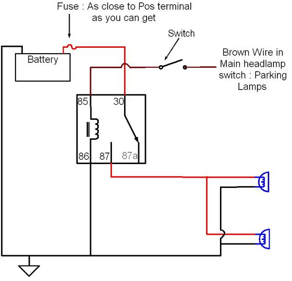
The lead from the battery has a fuse as close to the pos terminal on the battery as you can get it. The fuse size should be 15 AMPs ( 80% of fuse value = load ). Direct to battery terminal, don't try to piggy back any of the wires on the truck !.
The wire size for from the battery to the relay Pin #30 and from relay pin # 87 to the lights as well as the ground wires on the lamps should be a minimum of 16 AWG ( in automotive wire not HD wire ) , I would suggest 14 AWG ( HD wire ok in this size ).
Yes, there is a switch for the "switch" This is how you use a low amp switch to control a high amp load ( i.e that is a relay ).
You need to follow the diagram, from your text you are missing a few things.
If you can't follow this, you might want to think about having a place wire them for you. It can't get much more simple then either of the diagrams that I posted. Use a good quality crimper, and get the correct size crips for the battery terminal, and wire ( don't try to cram pink terminal ends on 14 AWG wire ).
The lead from the battery has a fuse as close to the pos terminal on the battery as you can get it. The fuse size should be 15 AMPs ( 80% of fuse value = load ). Direct to battery terminal, don't try to piggy back any of the wires on the truck !.
The wire size for from the battery to the relay Pin #30 and from relay pin # 87 to the lights as well as the ground wires on the lamps should be a minimum of 16 AWG ( in automotive wire not HD wire ) , I would suggest 14 AWG ( HD wire ok in this size ).
Yes, there is a switch for the "switch" This is how you use a low amp switch to control a high amp load ( i.e that is a relay ).
You need to follow the diagram, from your text you are missing a few things.
If you can't follow this, you might want to think about having a place wire them for you. It can't get much more simple then either of the diagrams that I posted. Use a good quality crimper, and get the correct size crips for the battery terminal, and wire ( don't try to cram pink terminal ends on 14 AWG wire ).