 |
Extending Fog/Driving Lamp Functionality in the 2000 SVT F-150 Lightning...
Contributed by Rick C |
Pin/Wire Descriptions
| PIN# |
WIRE COLOR |
FUNCTION |
| 1 |
- |
- |
| 2 |
white/black |
Input to foglamp switch, activates relay |
| 3 |
- |
- |
| 4 |
- |
- |
| 5 |
yellow |
Output from foglamp switch
|
| 6 |
black |
Ground pin |
| 7 |
green/red |
Output from autolamp switch, activates autolamp control circuitry (?) |
| 8 |
blue/orange |
Input to autolamp & headlamp switches |
| 9 |
red/yellow |
Output from headlamp switch, activates relay |
| 10 |
brown/white |
Input to parkinglamp switch |
| 11 |
white/red |
Output from parkinglamp switch, activates (?) |
| 12 |
brown |
Output from parkinglamp switch, activates relay |
Pin Logic at Various Switch Positions
| PIN# |
AUTO(OFF) |
AUTO(ON) |
OFF |
PARK |
ON |
FOG |
| 1 |
- |
- |
- |
- |
- |
- |
| 2 |
0 |
1 |
0 |
0 |
1 |
1 |
| 3 |
- |
- |
- |
- |
- |
- |
| 4 |
- |
- |
- |
- |
- |
- |
| 5 |
0 |
0 |
0 |
0 |
0 |
1 |
| 6 |
0 |
0 |
0 |
0 |
0 |
0 |
| 7 |
1 |
1 |
0 |
0 |
0 |
0 |
| 8 |
1 |
1 |
1 |
1 |
1 |
1 |
| 9 |
0 |
1 |
0 |
0 |
1 |
1 |
| 10 |
1 |
1 |
1 |
1 |
1 |
1 |
| 11 |
0 |
0 |
0 |
1 |
1 |
1 |
| 12 |
0 |
1 |
0 |
1 |
1 |
1 |
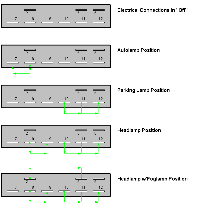
In this logic diagram, the 0 = approx. 0 Volts when measured against ground, and the 1's = approx. 12 Volts
Electrical Connections in Headlamp Switch
at Various Switch Positions

Back to 2000 SVT F-150 Lightning Foglight Mod
|

