 |
So you want to add some electrical accessories to your new truck... |
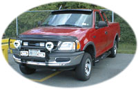 This series of "How-To's" covers information regarding vehicle electrical systems and electrical add-ons. It will sometimes refer to items that are specific to a 1997 Ford F-150 4x4. Not because I'm prejudiced - it's just that's what I currently drive and what I'm somewhat familiar with. Since most trucks/cars are similar, the formula's, procedures, hints and ideas are applicable to just about any installation. Hopefully everyone will be able to find something that'll be of use.
Before we go too far, let's cover some basics.
|
Definitions/Concepts/Formulas: Ampere (aka amps)- some sources define an ampere as the rate at which current flows through a circuit. This flow is greatly affected by conductor size (see RESISTANCE). It is more useful when "amps" are used to quantify the actual electrical consumption of each device connected to a particular circuit. Collectively, this consumption is also known as the "load", "draw" and/or "demand" of a circuit. Circuit- the path which electrical current follows. A simple circuit has a power source, a device or devices which use electricity, and a grounding point - all connected by conductors (typically wires). The rating of a circuit depends on the total draw of the connected devices (expressed in amps at a specific voltage). Usually a circuit is designed so that it's rating is about 10% higher than the connected load. This "safety factor" is included to cover starting surges (i.e. electric motors), circuit degradation and device efficiency issues. For example, a typical 12 volt circuit which "rated" for 20 amps, is actually designed for a total connected "load" of about 18 amps. This means that, designed properly, all of the devices connected to that particular circuit will use no more than 18 amps to operate, IF they are on all at once. The single most important thing to remember while designing a circuit is that an electrical device will attempt to draw the current that it needs to operate through the available circuit WHETHER OR NOT the circuit can handle the amperage. Conductors- the material through which electrical current flows. This is commonly via wire of various sizes, but a conductor can also be a bus bar or a terminal strip. Most wire used in vehicles is made of copper and is "stranded" (many small wires wrapped together to create one larger wire), but wire is also available in a single solid conductor up to certain sizes. The size of a conductor is crucial in designing a circuit (see RESISTANCE). The advantage of stranded wire conductors is that they are more flexible and are less susceptible to metal fatigue. Flexibility is important when routing cables around behind a dash and in an engine compartment. The constant vibrations and flex/movement that a vehicle encounters in everyday use (more so while off-road) may make metal fatigue an issue, but usually only at those junctures where wire mounting points can move independently of each other. Bending a solid wire back and forth will eventually cause it to break. "Metal fatigue" is seldom an issue with stranded wire unless it is severely corroded. Fuse- is a type of protection. No, not the latex kind. The kind that keeps the rest of your vehicle running when a short-circuit occurs elsewhere in the electrical system. There are a couple different types of fuses:
Fuses are rated in amps and correspond closely to the design capacity of the circuit. For example, a 15 amp fuse will accommodate approximately 15 amps regardless of what the circuit has been designed for. This is why it is important to use fuses that correspond to the circuit rating. There are different ways in which fuses operate. Most automotive fuses are designed to fail instantaneously if the circuit amperage exceeds the rating of the fuse. This is designed to protect the sensitive electronics now found in most vehicles. Some are the "slow-blow" type. These will accommodate a large in-rush of current without failing. Fusible Link- a piece of wire that is designed to "fail" when the amps being pulled thru it are greater than what the circuit was sized for. The drawback is that since this fusible link typically appears to be nothing more than an insulated section of wire, it is not always obvious that it has failed. The advantage is that the fusible link will usually not "fail" instantaneously if there is a momentary surge in a circuit (i.e. electric motor startup). Usually, fusible links are used on higher amp draw circuits but with the advent of the Maxi-Fuse, they are now used primarily for "slow-blow" applications. Fuse Tap- a device which slides into an existing fuse slot and is used to extract power from an existing circuit without splicing into the conductors of that circuit. Gauge- a measurement of wire size. "Gauge" is shorthand for AWG (American Wire Gauge) but is also commonly abbreviated as ga. Wire is also sometimes indicated with a "#" designation, especially in the single digit sizes (i.e. "#6 wire"). This is still wire of a certain gauge, but a type of slang usage has evolved over time. Automotive wire is often referred to as "primary wire" and is readily available in "even number" increments (2, 4 ,6, etc.). The smaller the gauge-number, the larger the diameter of the wire conductor. For instance, a 12-gauge (or 12 AWG) wire is actually larger than a 20 gauge wire, much like a 12-gauge shotgun shell is larger than a 20 gauge. There are even larger gauge wires, referred to as cables, which are indicated by a number-slash-zero designation. This is also known as "ought" sizes (i.e. "double-ought" for 2/0 cable). These are typically used for things like battery and starter cables. They allow a lot of electricity to flow with very little restriction, but are much larger than other wiring. Insulator- a shield from electrical flow. This is the vinyl, plastic or rubber coating on most wires and on the crimp connectors used at most connections. It can also be the heat shrinkable sleeves used on wire to wire splices, as well as those plastic corrugated "looms" that bundle several wires together. The purpose of this shield is to:
If the electrical flow of a circuit is "grounded" before it reaches a device, then the device won't get any "juice". In a worse case scenario, the "short-circuit" could create sparking and possibly a fire or explosion. At the very least, it could cause a nasty shock for someone trouble-shooting the problem. Mostly likely, it'll just keep something from running properly. Ohm- the measure of RESISTANCE in an electrical circuit. Ohm's Law- the relationship of volts, amperes and resistance. It states that when the force of one volt pushes one amp through a circuit, there will be one ohm of resistance. It can be expressed three ways:
Based on the fact that an automotive electrical system is typically a 12 volt system, the basic concept is that, given a specific amp draw, the smaller the conductor, the greater the resistance. Wire size is a function of amp draw versus resistance. This resistance is measured in ohm's. Someone figured out the nominal amount of resistance per lineal foot of some typical copper wire sizes and they're as follows:
Using Ohm's Law, you can use the amperage draw of the device to analyze the total resistance and voltage drop of the circuit. The trick is to keep the total circuit voltage drop to about 0.5 volts or less. I'm not sure why 0.5v is the magic number but suffice it to say that it is. Let's assume that you are laying out the wiring for a pair of off-road lights (about 12 amps total for both). You intend to use 14 gauge wire, and the total length of wire run will be about 16 feet from source-to switch-to lights. 16 feet x 0.0028 ohm/foot = 0.0448 ohms of resistance in a 14 ga. wire for that length. 12 amps x 0.0448ohms = a 0.5376 volt drop. Slightly over 0.5, but still acceptable. 14 ga. wire will be OK. Instead of figuring this out every time you analyze a circuit, Appendix B contains a couple of charts which are extremely useful in sizing wires for certain amp demands and distances. Note: these charts assume copper wire. Aluminum and copper clad- aluminum wire is available, but these are of minimal value for use in vehicles since they have more resistance than copper wiring and would therefore need to be larger than copper for a circuit with the same amp draw. Power Source- the starting point of a circuit. This is where electrical energy is either created or introduced via a stored supply. In vehicles, the alternator (which creates electricity) and the battery (which stores the electricity that the alternator produces) are the main power sources available. Additionally, power for new circuits can be derived from an existing circuit, but these new circuits are limited to whatever the rating of the existing circuit is (see ampere). Existing circuits can be connected into by various methods. They can be "tapped" (via a fuse box for example - see FUSE TAP). They can also be "spliced" into. This can be done by actually stripping the insulation from the existing wire and wrapping a new wire around the existing wire. This wrap splice can then be soldered if you want to, and then covered w/ "heat shrink" sleeves or electrical tape. Another method is to use a mechanical "tap". These "taps" have a notched metal plate inside them that cuts the insulation on each wire and makes contact w/ the conductor. You use a pair of pliers to squeeze the tap closed. If you are planning to use relays to power a number of devices or a large demand device, a very effective and convenient point to use as a power source is the PDT (power distribution terminal). The PDT is located on the starter solenoid and it's nice because:
Relay- a device used to control a large amount of energy with a much smaller amount of energy. Think of a relay as an electrically controlled on/off switch. You use a small amount of control current to energize a coil which in turn completes a different circuit of much larger current. The real advantage of a relay is that you are not running high amp current from the source, to a switch then to the device(s). The non-relay arrangement has a number of draw backs. The first is line loss due to resistance (remember, length adds to total circuit resistance). In order to overcome the distance from the power source to the switch, and from the switch to the device, the conductors will need to be larger. Another drawback is that the switch and connectors will need to be rated to handle the same number of amps as the rest of the circuit. Also, if the conductors are large (to accommodate the load), and if you have a number of devices, these conductors will take up a lot of room – something to consider while trying to fit everything behind the dash or get thru the firewall. Let's take a look at an example. A simple lighting circuit for two 100W lites mounted on a grille guard. This will entail running a fairly large conductor (16 ga. +/-) from the PDT, Battery or Alternator to an on/off switch in the cab, then back out to the lites (14' or so). If you use a relay, then you can use 20 ga. wire from the PDT/battery or alternator to the relay, and then to the lites. This routing is the "power circuit". To control the relay, you could use 24 or 26 ga. wire since the "control circuit" for a typical automotive relay draws about 1/10th an amp to energize the coil! This will be really be beneficial if there are a number of circuits being controlled and if there is a large distance from source-to-switch-to-device. Resistance- is a restriction in the electrical path. It prevents "the juice" from getting to where you need it, and typically creates heat. A lot of resistance will create a lot of heat, which may melt the insulators and fry your electrical system. The single most critical element in determining circuit resistance is conductor size. Resistance is expressed in Ohm's, and usefully corresponds to how much a certain size conductor will restrict the flow of electricity at a specific voltage and amperage. This amount of restriction is sometimes referred to as "line loss". The key to circuit design is to create a pathway large enough to accommodate the power required. Increase the conductor size (decrease the wire gauge #) and you lower the resistance of that conductor. The other critical element in resistance is the length of the circuit. It's simple, keep it as short as possible. Refer to Appendix B for some Wire Gauge Selection Charts. These charts take into account the resistance for specific wire sizes and will serve as guides to determine adequate conductor size for a given amp draw over a certain distance. The design of electrical circuits is a matter of efficiency. For example, sized "efficiently" - you may only need 16 ga. wire for a particular circuit. You could instead run #4 wire everywhere, and then use fuses that are sized for the actual connected load. Since the conductors could potentially carry more electrical current than what the fuses are rated for, these fuses would act as a "choke point. This format is usually more expensive than sizing the conductor properly for the overall distance and demand. Even if cost isn't a concern, if you have a number of devices to hookup, the space that a #4 wire takes up is 16 times that of a 16 ga. Put a bunch of #4 wires together and it's obvious that trying to get everything to fit may be a problem. Resistance also comes into play at connections and taps. Some people argue that soldered connections are a must for good current flow. Others argue that if done improperly, the heat of soldering can make the conductor more brittle. It's a matter of opinion and preference. Audiophiles want "clean" uninterrupted power flow. The off-road guys are worried about flex, vibration, durability and being weather-tight. The bottom line is to keep the connections, splices and taps to a minimum, size the conductors properly, and 99% of the time you'll be fine. Switch- a device used to control a circuit. Usually a switch is simply used to turn a simple circuit on and off, but there are opportunities to utilize complex control arrangements of multiple switches to control other switches. I will get into more detail on complex control arrangements in future articles, but here is a listing of some different types of switches available: (refer to Appendix A for schematic illustrations of these switches)
Listed below are several variations to the basic switch types:
Voltage- the measure of electrical force. The typical vehicle electrical system is a 12 volt system. Note that this is a nominal value. Most alternators (see POWER SOURCE) put out between 13 to 13.5 volts. The 1 volt or so drop is due to a number of factors and the 12 volt value is what you should utilize if you plan on hooking up to the vehicle's stock electrical system as a power source (this means "after" the battery). If you connect a new wiring setup to the alternator, then the actual alternator output voltage is a consideration. Watts- the measure of electrical power. Most electrical devices are denoted by a certain wattage output (i.e. lamps - 55 watt, 100 watt, etc.). The higher the wattage, the greater the amp draw of the device. (Remember, Amps = Watts/Voltage, where voltage is a constant 12 volts +/-) | ||||||||||||||
Here's a another very useful formula: Amps = Watts/Voltage.
This formula comes in handy when you want to determine the total demand of a circuit when you know the wattage of the attached devices. Let's say that you have a pair of 55 watt fog lamps. Given that most vehicle electrical systems are 12 volt, we can figure the amp "draw" of these two devices. Amps = (55 watts*2 lights) / 12 volts or 110 / 12 = 9.167 amps
You could "tap" an existing circuit that has about 10 amps of extra capacity. This would be "marginally acceptable" because there is very little or no "safety factor" built into the circuit. A more appropriate method would be to install a new circuit that is sized with a 10% +/- safety factor. A circuit that has 10% higher capacity would be slightly larger than 10 amps, so the design of this circuit should be for about 11 to 12 amps. Better to error on the side of caution.
Now that you know some of the lingo and concepts, before you can really impress the counter person at your local parts shop, you need to do some more research regarding your specific vehicle.