S331 Gauge Pod?
#16
 01-21-2012, 02:02 PM


Well, I FINALLY got the correct harness and the gauge is working PROPERLY!!!! Thanks to Tony at Saleen Performance for getting the P/Ns.
For future use by others; the P/N for the pod harness is 08-1704-B14832C, and Map Sensor (Reference) is 00-1702-C149940. You need both of these parts along with the gauge pod and all will be perfect.
Although I had it slightly working (inaccurate) without the parts, this is much much better!!!!
For future use by others; the P/N for the pod harness is 08-1704-B14832C, and Map Sensor (Reference) is 00-1702-C149940. You need both of these parts along with the gauge pod and all will be perfect.
Although I had it slightly working (inaccurate) without the parts, this is much much better!!!!
#17
01-22-2012, 10:06 AM

http://speedlab.saleen.com/store.cfm?store_id=1
You'll have to call them and give them the part #'s.
You'll have to call them and give them the part #'s.
#18
06-26-2012, 11:42 PM

#19
06-27-2012, 09:37 AM
Sorry to dig this thread up. BUT!
So the boost data is gathered from a seperate MAP sensor on a Saleen SC kit?
What about the IAT? Does it use the SC IAT sensor?
OEM is the MAP integrated into the Fuel rail pressure / Temp sensor? There's a line running from the manifold to this sensor!
So the boost data is gathered from a seperate MAP sensor on a Saleen SC kit?
What about the IAT? Does it use the SC IAT sensor?
OEM is the MAP integrated into the Fuel rail pressure / Temp sensor? There's a line running from the manifold to this sensor!
The boost data is gathered by using (two) MAP sensors; one in the top of the S/C (TMAP) and one located at the gauge pod. The MAP inside the vehicle is reference and when the MAP in the S/C "sees" boost, the corresponding difference moves the needle to show boost. At least this is my understanding and it works in my truck.

The IAT does come from the MAP (TMAP) in the top of the S/C. The (gray) wire from the MAF ("Air Flow Sensor") is cut and gets hooked to the MAP (TMAP harness) along with the gray/red from the MAF.
The sensor you are referring to that has the line from the manifold attached to it, is the (Fuel Rail Pressure Sensor). This is the OEM set-up and is also the same set-up with the S/C. The difference is that the TMAP in the S/C is "spliced" into the fuel pressure sensor harness at the brown/white (BVREF) wire.
George
Last edited by Jetpilot2; 06-27-2012 at 09:40 AM.
#20
07-10-2012, 10:25 PM
It has been awhile since I did the S/C install and I'm currently "away" from my truck for a couple months, but will do my best to help.
The boost data is gathered by using (two) MAP sensors; one in the top of the S/C (TMAP) and one located at the gauge pod. The MAP inside the vehicle is reference and when the MAP in the S/C "sees" boost, the corresponding difference moves the needle to show boost. At least this is my understanding and it works in my truck.
The IAT does come from the MAP (TMAP) in the top of the S/C. The (gray) wire from the MAF ("Air Flow Sensor") is cut and gets hooked to the MAP (TMAP harness) along with the gray/red from the MAF.
The sensor you are referring to that has the line from the manifold attached to it, is the (Fuel Rail Pressure Sensor). This is the OEM set-up and is also the same set-up with the S/C. The difference is that the TMAP in the S/C is "spliced" into the fuel pressure sensor harness at the brown/white (BVREF) wire.
George
I ended up buying AEM digi - analog gauges.
Well they require a full time live, Switched live, Ground and dimmer feed.
I can test the wiring no problem. Just wonder if anyone knows which wires are:
1) Full time +
2) Switched +
3) Ground (Black)
4) Illumination (Light Blue / Red)
Grey / Yellow: Is that full time or switched power?
#21
07-11-2012, 08:32 AM
#22
07-11-2012, 02:03 PM
#23
07-16-2012, 09:07 AM
#25
07-16-2012, 01:05 PM

#26
07-16-2012, 04:39 PM
Aye great. My KC should be here anytime
Now. I have a few ideas on location as its not a large unit at all.
You snooze you loose as they say, hope you got the deal price the Twinskrew got and hasn't used.
Am gonna plumb a temp sensor into the cold side.
Now. I have a few ideas on location as its not a large unit at all.
You snooze you loose as they say, hope you got the deal price the Twinskrew got and hasn't used.
Am gonna plumb a temp sensor into the cold side.
Last edited by Ross-FX4; 07-16-2012 at 04:50 PM.
#27
07-20-2012, 08:58 PM
#28
07-21-2012, 06:13 AM
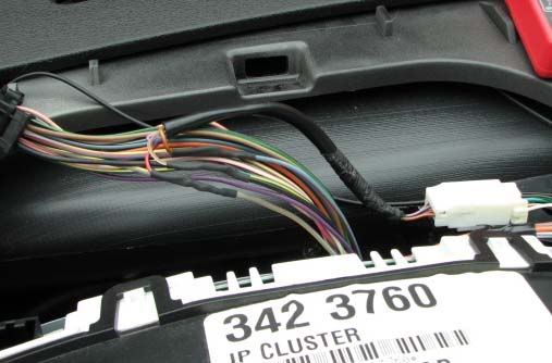
It should be BK w/LG stripe. The GY/LE should be switched when in RUN, also, RD/YE is switched.
Where are you looking "exactly". If you can't find BK/LG, you may be looking somewhere else. The '08 should be identical. Mine is an '07 and I have been using this '05 manual and everything has matched.
You see GY/YE and BK/LG (spliced) in the pic below.

#29
07-21-2012, 07:49 AM
Ross,
It should be BK w/LG stripe. The GY/LE should be switched when in RUN, also, RD/YE is switched.
Where are you looking "exactly". If you can't find BK/LG, you may be looking somewhere else. The '08 should be identical. Mine is an '07 and I have been using this '05 manual and everything has matched.
You see GY/YE and BK/LG (spliced) in the pic below.
Don't know what's going on fella. I studied the pic above as
Well as others but couldn't find the Black / Green stripe. The Grey / Yellow stripe was dead in all positions. I was going to splice into the left harness on the cluster.
Long shot: Can you remember pin positions for the wires?
Anyhow I will try again on days off. I was thinking about going off the Radio as the wires are just below the gauge assembly.
Thanks anyway. Will update when I can.
Ross