3157 & 194 Switchback LED bulbs and LOGO courtesy lights
#16
 03-13-2013, 01:19 PM


Join Date: Mar 2013
Location: Tampa Bay, Fl
Posts: 24
Likes: 0
Received 0 Likes
on
0 Posts
http://superlumination.com/switchback.html
FYI, The 194's are much more involved to get them to work because of the reversing polarity that is required.
DPDT relays and some diodes will have to be added to your parts list. I got the relays and diodes from Radio Shack.
Last edited by ag3ntorang3; 03-13-2013 at 01:24 PM. Reason: added more info

#18
03-13-2013, 08:03 PM
Join Date: Mar 2013
Location: Tampa Bay, Fl
Posts: 24
Likes: 0
Received 0 Likes
on
0 Posts
#19
03-13-2013, 10:34 PM
Join Date: Mar 2013
Location: Tampa Bay, Fl
Posts: 24
Likes: 0
Received 0 Likes
on
0 Posts
Ok, let's see if I can explain this.
In order for the 194 Switchback bulb to operate correctly, the polarity +/- of the input signals (turn circuit and park circuit) to the bulb must be reversed. To accomplish this, a DPDT (double pole, double throw) relay is used in conjunction with several diodes. The relay allows the input signals to be "criss-crossed" which results in the reversed polarity. The diodes prevent unwanted feedback (park circuit interferring with the turn circuit and vice versa).
There are 2 types of relays that can be used. The original author of the diagram below used a mini relay http://www.radioshack.com/product/in...ductId=2062483 and soldered the wiring and diodes to it. It is relatively cheap, but not the easiest thing to work with because of its small size.
I used this relay http://www.radioshack.com/product/in...ue=RadioShack#, which is similar in size to a standard automotive relay. It's easier to work with and you can use 1/4" insulated female connectors to terminate the wiring, but it's 2x the cost.
Which ever style you decide to use you'll need 2 of them, 1 for the left side corner light and 1 for the right side.
I used these diodes http://www.radioshack.com/product/in...ductId=2062578, you'll need 8 of them, 4 for each relay. The size of the diode (3 amp) is probably overkill, but it's what they had in stock at the time. You could probably use a 1 amp and be fine.
In case the links don't work, here is a materials list:
Qty. (2) - 12VDC/10A DPDT Plug-in Relay
Radio Shack Model: 275-218 | Catalog #: 275-218
Qty. (8) - 3 Amp Diodes
Radio Shack Model: 1N5402 | Catalog #: 276-1143
Qty. (16) - 1/4" Insulated Female Spade wire connectors
Qty. (6) - butt connectors
Now the fun part, wiring it up:
I'll try to explain the diagram below first.
I found the original diagram while I was researching how to make this work on my truck. I then added the red and green scribbles to try and clarify the process.
The large black rectangle in the middle of the diagram is the relay, looking at it from the bottom. The numbers correspond to the male terminals and are imprinted on the mini relay. The relay I used has different numbers next to its terminals, but the process is the same.
The diodes (4 of them) are the triangular symbols with +/- on them. It is important to wire these in the correct orientation. If you put one in backwards, the circuit won't work properly. When physically looking at a diode, the silver band indicates the (-) side of the diode.
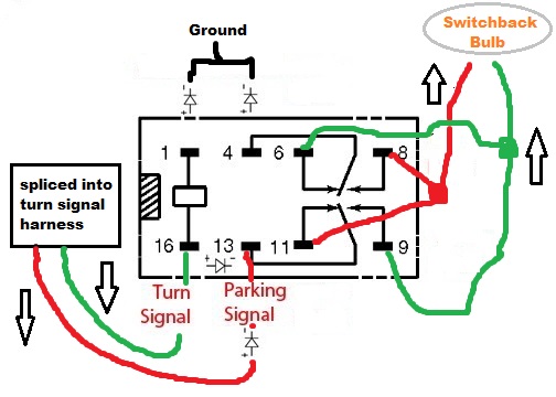
Ok, that's it for tonight...hit post instead of preview... Hopefully, this is making some sense. I'll try to finish it up tomorrow.
In order for the 194 Switchback bulb to operate correctly, the polarity +/- of the input signals (turn circuit and park circuit) to the bulb must be reversed. To accomplish this, a DPDT (double pole, double throw) relay is used in conjunction with several diodes. The relay allows the input signals to be "criss-crossed" which results in the reversed polarity. The diodes prevent unwanted feedback (park circuit interferring with the turn circuit and vice versa).
There are 2 types of relays that can be used. The original author of the diagram below used a mini relay http://www.radioshack.com/product/in...ductId=2062483 and soldered the wiring and diodes to it. It is relatively cheap, but not the easiest thing to work with because of its small size.
I used this relay http://www.radioshack.com/product/in...ue=RadioShack#, which is similar in size to a standard automotive relay. It's easier to work with and you can use 1/4" insulated female connectors to terminate the wiring, but it's 2x the cost.
Which ever style you decide to use you'll need 2 of them, 1 for the left side corner light and 1 for the right side.
I used these diodes http://www.radioshack.com/product/in...ductId=2062578, you'll need 8 of them, 4 for each relay. The size of the diode (3 amp) is probably overkill, but it's what they had in stock at the time. You could probably use a 1 amp and be fine.
In case the links don't work, here is a materials list:
Qty. (2) - 12VDC/10A DPDT Plug-in Relay
Radio Shack Model: 275-218 | Catalog #: 275-218
Qty. (8) - 3 Amp Diodes
Radio Shack Model: 1N5402 | Catalog #: 276-1143
Qty. (16) - 1/4" Insulated Female Spade wire connectors
Qty. (6) - butt connectors
Now the fun part, wiring it up:
I'll try to explain the diagram below first.
I found the original diagram while I was researching how to make this work on my truck. I then added the red and green scribbles to try and clarify the process.
The large black rectangle in the middle of the diagram is the relay, looking at it from the bottom. The numbers correspond to the male terminals and are imprinted on the mini relay. The relay I used has different numbers next to its terminals, but the process is the same.
The diodes (4 of them) are the triangular symbols with +/- on them. It is important to wire these in the correct orientation. If you put one in backwards, the circuit won't work properly. When physically looking at a diode, the silver band indicates the (-) side of the diode.
Ok, that's it for tonight...hit post instead of preview... Hopefully, this is making some sense. I'll try to finish it up tomorrow.
Last edited by ag3ntorang3; 03-13-2013 at 10:40 PM. Reason: blah
#20
03-14-2013, 09:17 PM
Join Date: Mar 2013
Location: Tampa Bay, Fl
Posts: 24
Likes: 0
Received 0 Likes
on
0 Posts
I revised the the diagram above with the correct pin numbers on the relay I used. Here is the new diagram:
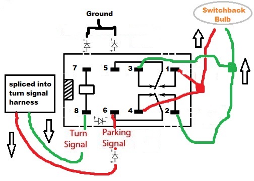
Pins 7 & 5 get diodes and go to ground.
Pin 8 goes to the turn signal wire harness on the headlight housing and gets spliced into the turn signal (+) wire.
Pin 6 also goes to the turn signal wire harness and gets spliced into the park light (+) wire with a diode.
Add a diode from pin 8 to pin 6.
Pins 3 & 2 get wired together and go to the 194 socket. This will be the wire that operates the amber side of the switchback.
Pins 4 & 1 get wired together and also go to the 194 socket. This will be the wire that operates the white side of the switchback.
I basically wired the relay as a stand alone unit with the diodes attached to it (observing their correct orientation) and the wire leads that have to run to ground, the turn signal harness and 194 socket terminated with disconnects that allow them to be spliced in or connected. (I should have taken pictures during the install so this would make more sense).
I cut the the original 194 wires about 4" back from the socket and attached the wires that run from pins 1 & 2 to those 4" wires. Connect your ground and then splice into the turn signal harness. Plug the switchback bulb into the socket and test it out. If the bulb lights up amber for parking or white for turn, just pull it out and turn it around.
I hope this all makes some sense. It's not as complicated as I probably made it sound. Good luck!
#21
03-15-2013, 06:39 AM
I revised the the diagram above with the correct pin numbers on the relay I used. Here is the new diagram:
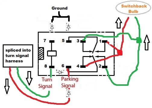
Pins 7 & 5 get diodes and go to ground.
Pin 8 goes to the turn signal wire harness on the headlight housing and gets spliced into the turn signal (+) wire.
Pin 6 also goes to the turn signal wire harness and gets spliced into the park light (+) wire with a diode.
Add a diode from pin 8 to pin 6.
Pins 3 & 2 get wired together and go to the 194 socket. This will be the wire that operates the amber side of the switchback.
Pins 4 & 1 get wired together and also go to the 194 socket. This will be the wire that operates the white side of the switchback.
I basically wired the relay as a stand alone unit with the diodes attached to it (observing their correct orientation) and the wire leads that have to run to ground, the turn signal harness and 194 socket terminated with disconnects that allow them to be spliced in or connected. (I should have taken pictures during the install so this would make more sense).
I cut the the original 194 wires about 4" back from the socket and attached the wires that run from pins 1 & 2 to those 4" wires. Connect your ground and then splice into the turn signal harness. Plug the switchback bulb into the socket and test it out. If the bulb lights up amber for parking or white for turn, just pull it out and turn it around.
I hope this all makes some sense. It's not as complicated as I probably made it sound. Good luck!
Pins 7 & 5 get diodes and go to ground.
Pin 8 goes to the turn signal wire harness on the headlight housing and gets spliced into the turn signal (+) wire.
Pin 6 also goes to the turn signal wire harness and gets spliced into the park light (+) wire with a diode.
Add a diode from pin 8 to pin 6.
Pins 3 & 2 get wired together and go to the 194 socket. This will be the wire that operates the amber side of the switchback.
Pins 4 & 1 get wired together and also go to the 194 socket. This will be the wire that operates the white side of the switchback.
I basically wired the relay as a stand alone unit with the diodes attached to it (observing their correct orientation) and the wire leads that have to run to ground, the turn signal harness and 194 socket terminated with disconnects that allow them to be spliced in or connected. (I should have taken pictures during the install so this would make more sense).
I cut the the original 194 wires about 4" back from the socket and attached the wires that run from pins 1 & 2 to those 4" wires. Connect your ground and then splice into the turn signal harness. Plug the switchback bulb into the socket and test it out. If the bulb lights up amber for parking or white for turn, just pull it out and turn it around.
I hope this all makes some sense. It's not as complicated as I probably made it sound. Good luck!
Thank You again for the diagram and instructions...sounds like another project for when it warms up here in the north.. I appreciate it..

#22
03-15-2013, 09:34 PM
Join Date: Mar 2013
Location: Tampa Bay, Fl
Posts: 24
Likes: 0
Received 0 Likes
on
0 Posts
#23
03-20-2013, 09:18 PM

Senior Member
Join Date: Jan 2006
Location: Howell, NJ
Posts: 410
Likes: 0
Received 0 Likes
on
0 Posts
Just so Im understanding this, the 194 bulbs are the side markers in your headlights right. And did you originally have amber lenses on them that just lit up with your parking lights but didnt blink with the blinkers. Cause the set of heads im getting retrofitted have the clear side marker lenses and this would be a cool mod if Im understanding it right. Thanks for the detailed directions. How did you wire in the diode between the 8 and 6 pin.
#24
03-20-2013, 10:35 PM
Join Date: Mar 2013
Location: Tampa Bay, Fl
Posts: 24
Likes: 0
Received 0 Likes
on
0 Posts
Originally Posted by kitchenboy
Just so Im understanding this, the 194 bulbs are the side markers in your headlights right. And did you originally have amber lenses on them that just lit up with your parking lights but didnt blink with the blinkers.
Originally Posted by kitchenboy
How did you wire in the diode between the 8 and 6 pin.
Last edited by ag3ntorang3; 03-20-2013 at 10:47 PM.
#25
03-20-2013, 11:40 PM
Join Date: Mar 2013
Location: Tampa Bay, Fl
Posts: 24
Likes: 0
Received 0 Likes
on
0 Posts
#26
03-21-2013, 07:58 PM
Senior Member
Join Date: Jan 2006
Location: Howell, NJ
Posts: 410
Likes: 0
Received 0 Likes
on
0 Posts
Yeah I understand where it goes, but if you used male spades on the relay, how did you conect in the diode. Did you slip wires over the male terminals and then splice intoi those wires with the diode. Also if pin 7 and 5 both go to ground, why cant they just be spliced together and run through one diode and to a single grounding point.
#27
03-21-2013, 07:59 PM
Senior Member
Join Date: Jan 2006
Location: Howell, NJ
Posts: 410
Likes: 0
Received 0 Likes
on
0 Posts
#28
03-21-2013, 08:01 PM
Senior Member
Join Date: Jan 2006
Location: Howell, NJ
Posts: 410
Likes: 0
Received 0 Likes
on
0 Posts
#29
03-21-2013, 08:38 PM
Join Date: Mar 2013
Location: Tampa Bay, Fl
Posts: 24
Likes: 0
Received 0 Likes
on
0 Posts
I was thinking the same thing, but, when I found the original diagram while I was researching this project, it was wired in this configuration, so I just stuck with it. I think it would work fine though with terminals 7 and 5 wired to a single diode then to ground.
#30
03-21-2013, 08:42 PM
Join Date: Mar 2013
Location: Tampa Bay, Fl
Posts: 24
Likes: 0
Received 0 Likes
on
0 Posts

