Need help with installing power folding mirrors on my 2006 Lariat
#1
 09-02-2012, 10:43 PM


Join Date: Feb 2012
Location: San Antonio, TX
Posts: 246
Likes: 0
Received 0 Likes
on
0 Posts
Need help with installing power folding mirrors on my 2006 Lariat
Ok, let me first start off with everything I have done for the project so far.
I am installing power folding mirrors from a 2011 FX4 onto a 2006 Lariat (had non power folding mirrors)
Materials
Power folding mirrors - 2011 FX4
Power folding module - 5L3Z-17L684-AA
OEM power folding switch
Wire Pigtail - 3U2Z-14S411-AJA
Add a Circuit 10AMP - Going into F4 in the fuse box
18 Gauge wire - Had some 18/4 shielded wire that I broke down to individual strands.
Misc. connectors/tape etc
Now lets start with switching around the pins from a 2005 harness to a 2007
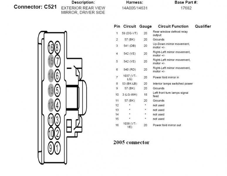
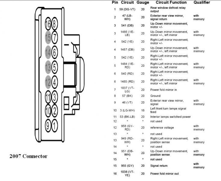
I removed pins 2 & 9 from my harness and connected them together into a single pigtail and tied it into pin 8 to correspond with the 2007 harness.
I then added a pigtail for pin slots 7 & 16 for power fold in and out.
Now the mirrors I bought do have puddle lamps. Heres the problem looking at the diagram for a 2005 it shows pin 8 is for the interior lamps switched power (puddle lamps). Well mine did not have a pin there or 11 which is a ground. So I ran a pigtail anyways to tie them in else where.
Both harnesses were set up exactly the same way to correspond with the 2007 harness.
I ran another pigtail from the factory switch (pin 4)
I ran all my wires into the cab from both sides in a central location (by the fuse box)
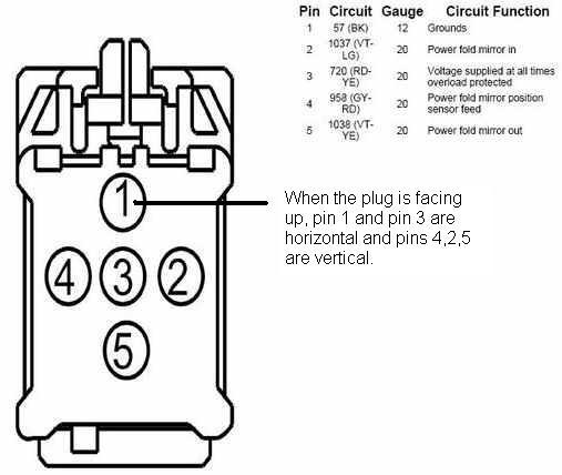
Now lets look at the wiring diagram for everything
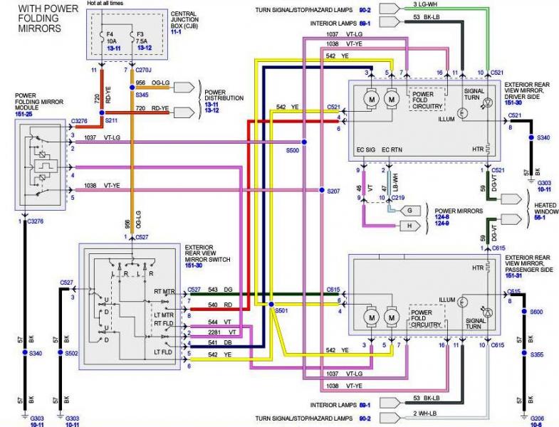
If you look to the left you will see how everything connects to the module.
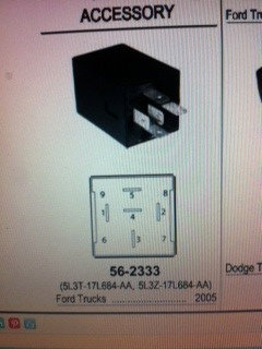
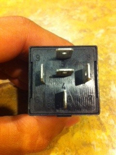
Now from what I have gathered on the forums the numbers that are on the module itself do not correspond with the numbers that go with the wiring diagram.
Here is the module, hopefully you can read the numbers on it
Here is some diagrams I found on the forums.

The other one I found was the same except it had 2 going to the factory switch and 4 being power fold in.
So now this is where I am confused. I've read if I follow the numbers that are actually on the module and correspond with the wiring diagram it will not work and will blow the module. I do not want that since it was around $75.
Now before I connected everything to the module I trimmed all my wires. I connected wires from driver/pass for pin 7 and made them into a single pigtail. I did the same thing for the wires coming from pin 16. I ran my add a circuit into the fuse box into F4, and ran a ground. I put female connectors on all them for the blades on the module.
I did follow the diagrams I found on the forums and here were my results
The first diagram everything worked but the mirrors did not fold in. When I went to try and fold them in Fuse 3 would blow.
The 2nd diagram still no power fold but no fuse blew.
So now I do not know what to do. Neither one of these diagrams worked for me and I am afraid to wire them up by the numbers on the module bc I do not want to blow it. If anyone has advice or suggestions please help me. I have about $500 into this mod so far and want them fully functional.
Issues
Can not get the mirrors to fold in due to ?
Did not have an exisiting wire for the puddle lamps so I need to know where else I can tie them in.
If there is anything else you guys need info wise please let me know.
Big thanks to SSCULLY for the wiring diagrams
I hope all this makes sense.
I am installing power folding mirrors from a 2011 FX4 onto a 2006 Lariat (had non power folding mirrors)
Materials
Power folding mirrors - 2011 FX4
Power folding module - 5L3Z-17L684-AA
OEM power folding switch
Wire Pigtail - 3U2Z-14S411-AJA
Add a Circuit 10AMP - Going into F4 in the fuse box
18 Gauge wire - Had some 18/4 shielded wire that I broke down to individual strands.
Misc. connectors/tape etc
Now lets start with switching around the pins from a 2005 harness to a 2007
I removed pins 2 & 9 from my harness and connected them together into a single pigtail and tied it into pin 8 to correspond with the 2007 harness.
I then added a pigtail for pin slots 7 & 16 for power fold in and out.
Now the mirrors I bought do have puddle lamps. Heres the problem looking at the diagram for a 2005 it shows pin 8 is for the interior lamps switched power (puddle lamps). Well mine did not have a pin there or 11 which is a ground. So I ran a pigtail anyways to tie them in else where.
Both harnesses were set up exactly the same way to correspond with the 2007 harness.
I ran another pigtail from the factory switch (pin 4)
I ran all my wires into the cab from both sides in a central location (by the fuse box)
Now lets look at the wiring diagram for everything
If you look to the left you will see how everything connects to the module.
Now from what I have gathered on the forums the numbers that are on the module itself do not correspond with the numbers that go with the wiring diagram.
Here is the module, hopefully you can read the numbers on it
Here is some diagrams I found on the forums.
The other one I found was the same except it had 2 going to the factory switch and 4 being power fold in.
So now this is where I am confused. I've read if I follow the numbers that are actually on the module and correspond with the wiring diagram it will not work and will blow the module. I do not want that since it was around $75.
Now before I connected everything to the module I trimmed all my wires. I connected wires from driver/pass for pin 7 and made them into a single pigtail. I did the same thing for the wires coming from pin 16. I ran my add a circuit into the fuse box into F4, and ran a ground. I put female connectors on all them for the blades on the module.
I did follow the diagrams I found on the forums and here were my results
The first diagram everything worked but the mirrors did not fold in. When I went to try and fold them in Fuse 3 would blow.
The 2nd diagram still no power fold but no fuse blew.
So now I do not know what to do. Neither one of these diagrams worked for me and I am afraid to wire them up by the numbers on the module bc I do not want to blow it. If anyone has advice or suggestions please help me. I have about $500 into this mod so far and want them fully functional.
Issues
Can not get the mirrors to fold in due to ?
Did not have an exisiting wire for the puddle lamps so I need to know where else I can tie them in.
If there is anything else you guys need info wise please let me know.
Big thanks to SSCULLY for the wiring diagrams
I hope all this makes sense.
Last edited by Mrocha85; 09-02-2012 at 10:53 PM. Reason: Adding Picture
#2
09-03-2012, 05:49 PM


Sorry have not had time to be on the site the past week.
Few things.
1. I removed pins 2 & 9 from my harness and connected them together into a single pigtail and tied it into pin 8 to correspond with the 2007 harness.
- You should not be splicing together pins #2 & #9, that is done in the mirror.
If you have these tied together, it looked like you have grounded the electronic chromatic part of the mirror.
2. Puddle lamps
- Where did you splice them ? It should only be the interior lamps to pin #11.
- In the How To forum there is a thread on locating the interior lamp circuit that you would wire pin #11 to.
3. The part number 5L3T-17L684-AA / 5L3Z-17L684-AA when looked up at Tasca shows as a 5 pin relay, not a power fold module ( also there is no tab for the factory harness connector ). Might want to verify this, as this looks like a SPDT 5 pin relay.
- Quick verification ( if it is not smoked already ) is to measure the ohms across pins #1 & 2. If it is 50 to 100 ohms, next check resistance on pins #3 to #4, it should show < 10 ohms ( if the battery in your meter is new ) and pin #3 to #5 will show infinity or open.
- If this is the case, you have a SPDT relay and would make sense why you are blowing the fuse.
That is about what I see so far.
#3
09-03-2012, 06:20 PM
Join Date: Feb 2012
Location: San Antonio, TX
Posts: 246
Likes: 0
Received 0 Likes
on
0 Posts
Sorry have not had time to be on the site the past week.
Few things.
1. I removed pins 2 & 9 from my harness and connected them together into a single pigtail and tied it into pin 8 to correspond with the 2007 harness.
- You should not be splicing together pins #2 & #9, that is done in the mirror.
If you have these tied together, it looked like you have grounded the electronic chromatic part of the mirror.
2. Puddle lamps
- Where did you splice them ? It should only be the interior lamps to pin #11.
- In the How To forum there is a thread on locating the interior lamp circuit that you would wire pin #11 to.
3. The part number 5L3T-17L684-AA / 5L3Z-17L684-AA when looked up at Tasca shows as a 5 pin relay, not a power fold module ( also there is no tab for the factory harness connector ). Might want to verify this, as this looks like a SPDT 5 pin relay.
- Quick verification ( if it is not smoked already ) is to measure the ohms across pins #1 & 2. If it is 50 to 100 ohms, next check resistance on pins #3 to #4, it should show < 10 ohms ( if the battery in your meter is new ) and pin #3 to #5 will show infinity or open.
- If this is the case, you have a SPDT relay and would make sense why you are blowing the fuse.
That is about what I see so far.
Few things.
1. I removed pins 2 & 9 from my harness and connected them together into a single pigtail and tied it into pin 8 to correspond with the 2007 harness.
- You should not be splicing together pins #2 & #9, that is done in the mirror.
If you have these tied together, it looked like you have grounded the electronic chromatic part of the mirror.
2. Puddle lamps
- Where did you splice them ? It should only be the interior lamps to pin #11.
- In the How To forum there is a thread on locating the interior lamp circuit that you would wire pin #11 to.
3. The part number 5L3T-17L684-AA / 5L3Z-17L684-AA when looked up at Tasca shows as a 5 pin relay, not a power fold module ( also there is no tab for the factory harness connector ). Might want to verify this, as this looks like a SPDT 5 pin relay.
- Quick verification ( if it is not smoked already ) is to measure the ohms across pins #1 & 2. If it is 50 to 100 ohms, next check resistance on pins #3 to #4, it should show < 10 ohms ( if the battery in your meter is new ) and pin #3 to #5 will show infinity or open.
- If this is the case, you have a SPDT relay and would make sense why you are blowing the fuse.
That is about what I see so far.
1. Ok, a little confused here. So looking at the harness setup for the 05 and 07. On the 05 its showing pins 2,9,11 are grounds. On the 07 its showing only 1 ground which is pin 8, so I'm assuming pin 8 in the new mirrors is a ground as well? or no?
Your saying not to splice pins 2 & 9 on my harness side, so do I just put the pins back in there original places and leave them as a ground? Or do I need to change the ground on the mirror side to be at pin 2 or 9?
2. Ok, I'll check out that how to. Thanks for that.
3. Indeed it is a relay, all these threads I've read call it a module. There is 2 threads that I have read that say that this is what I needed to make it work. I did not see anything else to go with it. Basically just slap some female blade connectors on the wires and put them on the relay.
Thanks again for the help SSCULLY
#4
09-03-2012, 06:37 PM
1. Pin #8 is the only ground, no need to splice them together
- Or at least that is what I got from :
If you are not wiring in the EC part of the driver's side, just leave them out.
3. Look at the guts of the power fold module in the diagram, that is not a diagram for a SPDT relay internals.
If you are doing a DIY you could go with relays or DPDT switches, but the factory module would have the tab for the connector and a base not designed to plug into the fuse panel.
I checked both with the diagram to relay conversion, and checking using the pin numbers in the diagram to the relay, and either way the coil is not being activated ( pins #1 & 2 on the relay you have ).
If it was activated by the coil, only 1 side is being changed from normally closed to normally open, so only 1 side would have the polarity changed ( both sides of the power fold motor need to be changed to change the direction from in to out ).
- Or at least that is what I got from :
I removed pins 2 & 9 from my harness and connected them together into a single pigtail and tied it into pin 8 to correspond with the 2007 harness.
3. Look at the guts of the power fold module in the diagram, that is not a diagram for a SPDT relay internals.
If you are doing a DIY you could go with relays or DPDT switches, but the factory module would have the tab for the connector and a base not designed to plug into the fuse panel.
I checked both with the diagram to relay conversion, and checking using the pin numbers in the diagram to the relay, and either way the coil is not being activated ( pins #1 & 2 on the relay you have ).
If it was activated by the coil, only 1 side is being changed from normally closed to normally open, so only 1 side would have the polarity changed ( both sides of the power fold motor need to be changed to change the direction from in to out ).
#6
09-03-2012, 10:06 PM
1. You could have just used a pin remover and moved 1 of the grounds to pin #8 location, but I guess if you connected both ground together on the truck's wiring and connected it to a single pin on #8 on the truck side of the connector, that is fine.
- The way it read made me think it was at the connector or after the mirror side connector that the splice was made. my confusion on the topic.
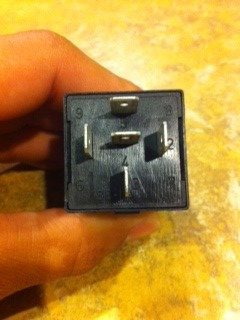
3. Take a test of that, and see if it is a SPDT relay, it looks like one.
The shape of it is not correct from the picture of the power fold module connector above ( that is a rectangle device with a key at one end, the picture you show is what I see called a full size ISO relay shape ( square ).
- The way it read made me think it was at the connector or after the mirror side connector that the splice was made. my confusion on the topic.
3. Take a test of that, and see if it is a SPDT relay, it looks like one.
The shape of it is not correct from the picture of the power fold module connector above ( that is a rectangle device with a key at one end, the picture you show is what I see called a full size ISO relay shape ( square ).
#7
09-03-2012, 10:28 PM
Join Date: Feb 2012
Location: San Antonio, TX
Posts: 246
Likes: 0
Received 0 Likes
on
0 Posts
Trending Topics
#8
09-04-2012, 09:56 PM
This is a connector ( connector view in the EVTM ) not a relay socket.
Relay sockets do not have a tab or keyed orientation to them.
The size is also wrong, it might be close to a half size ISO relay, which has a different pin orientation for a SPDT configuration.
#9
09-05-2012, 11:03 PM
Join Date: Feb 2012
Location: San Antonio, TX
Posts: 246
Likes: 0
Received 0 Likes
on
0 Posts
Man, told you I was a total noob to this lol.
Here's where I got my info from. This is where this whole ordeal came from, parts and all.
Post 172
https://www.f150online.com/forums/20...l-f150-12.html
First post
https://www.f150online.com/forums/20...s-04-f150.html
Here's where I got my info from. This is where this whole ordeal came from, parts and all.
Post 172
https://www.f150online.com/forums/20...l-f150-12.html
First post
https://www.f150online.com/forums/20...s-04-f150.html
#10
09-05-2012, 11:24 PM
#11
09-06-2012, 01:38 PM
Join Date: Feb 2012
Location: San Antonio, TX
Posts: 246
Likes: 0
Received 0 Likes
on
0 Posts
#12
09-14-2012, 10:20 PM
Join Date: Feb 2012
Location: San Antonio, TX
Posts: 246
Likes: 0
Received 0 Likes
on
0 Posts
Success! I got the mirrors to fold with the factory switch, the relay does work. I saw those things fold in and was in shock, couldn't believe my eyes. Now I just need to hook up my puddle lights (gotta follow SSCULLY's how to) and it's all done. I appreciate all the help guys.
The last picture diagram on my original post is a mirror image, so pin 2 & 4 are reversed.
The last picture diagram on my original post is a mirror image, so pin 2 & 4 are reversed.