Overhead Console Temp Display Repair
#61
 02-14-2011, 11:43 AM


Join Date: Sep 2009
Location: NC
Posts: 660
Likes: 0
Received 0 Likes
on
0 Posts
#62
02-14-2011, 01:19 PM

Member
Join Date: Nov 2010
Location: The Devil's Playground
Posts: 35
Likes: 0
Received 0 Likes
on
0 Posts
Be careful because the wiring harness is attached to it via a big connector, so you don't want to yank it down and have it hanging by the wiring harness.

I just carefully pried each corner down until it came down enough that I could stick my fingers in there and pull it evenly down the rest of the way. I've done it that way 3 times so far with no ill effects.
I have to take it down once again because I must not have pushed the resistor down on the PCB enough because it turned back off (or another one came up). I'll try and take pics of how I take it out this time.
#63
02-16-2011, 11:19 PM

Junior Member
Join Date: Feb 2011
Location: NEVADA
Posts: 2
Likes: 0
Received 0 Likes
on
0 Posts
#64
02-22-2011, 11:19 AM
Join Date: Sep 2009
Location: NC
Posts: 660
Likes: 0
Received 0 Likes
on
0 Posts
Ok, guys...finally took the plunge and got my overhead console off. Now I have a new problem. I of course have a 510 chip that is missing. I can NOT seem to find these chips. Went to Radio Shack and a local electronics store. Where are ya'll getting them at??? HELP!!!!!!!!!!!!!!!!----DirtySCREW
#65
02-22-2011, 11:35 AM

Ok, guys...finally took the plunge and got my overhead console off. Now I have a new problem. I of course have a 510 chip that is missing. I can NOT seem to find these chips. Went to Radio Shack and a local electronics store. Where are ya'll getting them at??? HELP!!!!!!!!!!!!!!!!----DirtySCREW
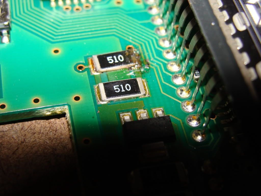
Take a look at post # 40 above, I show ( on a SuperDuty overhead console so they are 68 Ohm ) the normal resistor mounted to the PCB.
https://www.f150online.com/forums/4260712-post40.html
I just made a L at the bottom of the resistor and tint'd it so it was a quick hit with the soldering iron to get it on.
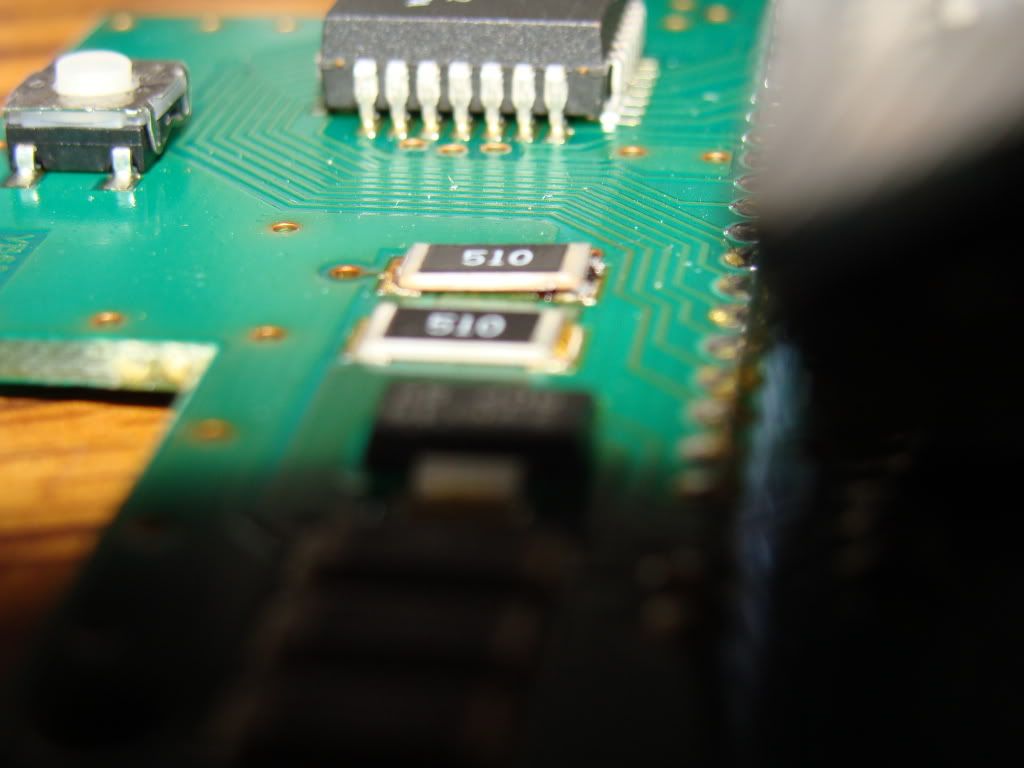
The surface mount resistor are used for wave soldering lines, they are the same 51 ohm resistor you can get anywhere ( the surface mount do a 510 to represent 51 ohm, not sure what the zero is for... same as the gold and silver stripes on a normal resistor ?? )


#68
02-22-2011, 09:10 PM
Join Date: Sep 2009
Location: NC
Posts: 660
Likes: 0
Received 0 Likes
on
0 Posts
#69
02-25-2011, 11:39 AM
Join Date: Sep 2009
Location: NC
Posts: 660
Likes: 0
Received 0 Likes
on
0 Posts
#70
02-25-2011, 02:17 PM
I think I would chance a 50 ohm, but 47 I do not know. Not sure what the resistors are for that are coming loose ( in the power path to the IC or from the OC to the display ), to know if going that low would be OK.
When I got the 68 ohm resistors for the SD overhead, I had to get a bag of resistors ( mixed values ) for ~ 5.00?
Do they have 2 100 ohm resistors ?
If you put these in parallel and then solder to the PCB, you would be making a 50 ohm resistor. That is closer to the 51.
I don't really know what is going to happen if you put a 50 in either.
If you twist 2 resistors in parallel the value is cut in half ( if they are the same ). If you put 2 resistors inline ( series ) the value is added.
Here is a page that describes the relationship ( had to go and find one ) and how the inverse relationship works.
http://www.electronics-tutorials.ws/resistor/res_4.html
Example No2 gives a good idea on how different values with the 2 resistors in parallel work.
#72
02-26-2011, 01:01 PM
Join Date: Sep 2009
Location: NC
Posts: 660
Likes: 0
Received 0 Likes
on
0 Posts
#73
02-26-2011, 05:00 PM
Join Date: Sep 2009
Location: NC
Posts: 660
Likes: 0
Received 0 Likes
on
0 Posts
#74
03-30-2011, 10:23 PM

Member
Join Date: Nov 2007
Location: Orlando, Fl
Posts: 74
Likes: 0
Received 0 Likes
on
0 Posts
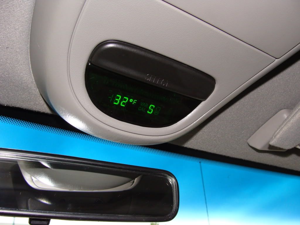
Mine stopped working a couple months ago. Took it apart and found 1 resistor hanging on by a hair. Asked the wife to fix it up for me since she use to repair electronic equipment full time. Works great now except the temp is a little off in cold weather... hot weather it displays the correct temp perfectly.
https://www.f150online.com/forums/me...d-display.html
https://www.f150online.com/forums/me...d-display.html
#75
05-21-2011, 07:49 PM

Junior Member
Join Date: May 2011
Location: Manitoba, Canada
Posts: 3
Likes: 0
Received 0 Likes
on
0 Posts
Does your console not light up anymore?
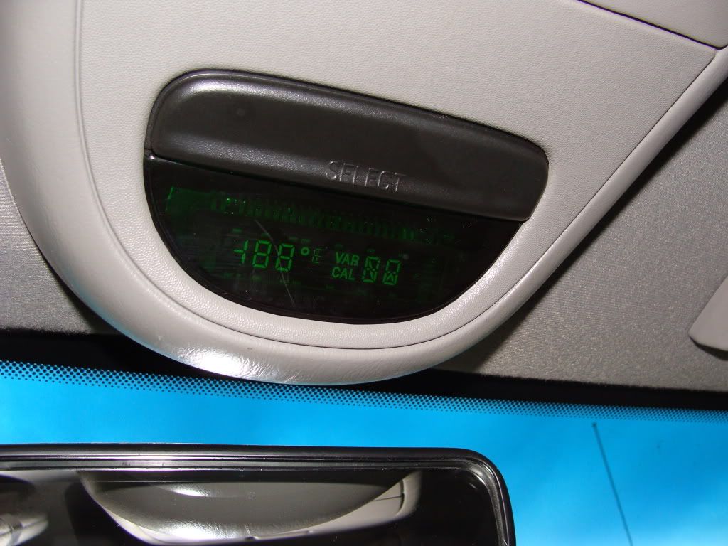
Before you start the process, cycle the button a couple times to make sure its not just turned off.
Tools needed:
#2 Phillips
T10 bit/driver
Soldering gun & solder
If you are not experienced with a soldering gun use caution, or let someone tackle this that knows how to do the repair safely.
I am not responsible for any damages to you or your truck, this is merely a guideline to go by, individual results may vary
Start by removing the Phillips screw located above the mirror
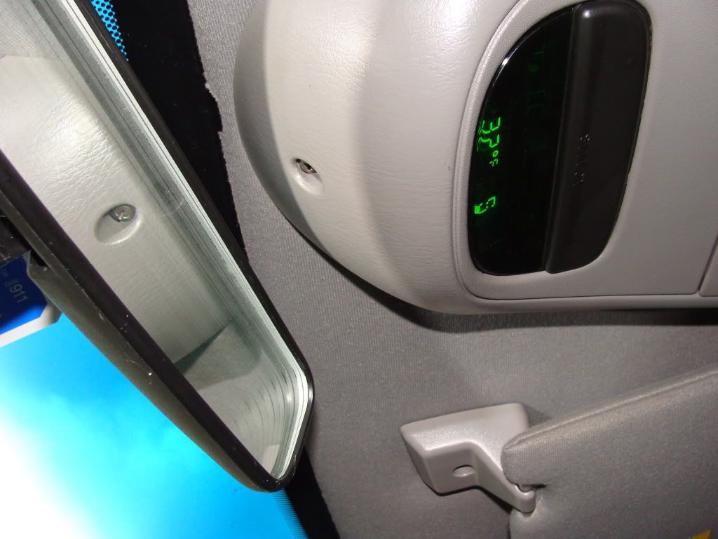
In the rear door, there are plastic tab that have a metal clip. (one on each side) But all you need to do is just grab the console firmly and pull straight down on it. The console will pop off, make sure you dont pull too hard or you risk damaging the wires on the display.
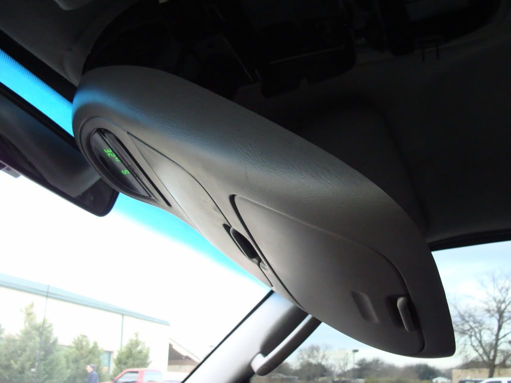
The wiring connector is just clipped on the display, just slide it straight right to left
Disconnect the wiring connector, and take the console to your work bench (tailgate) and prepare to disassemble it.
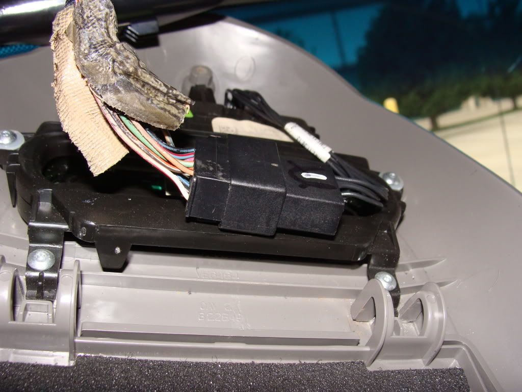
Next you will see the 4 T10 screws.
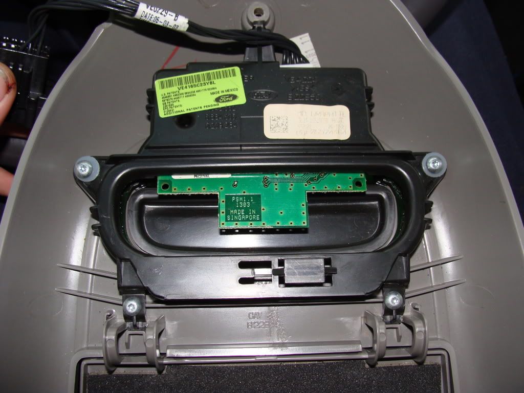
Once removed, you will have the entire display unit
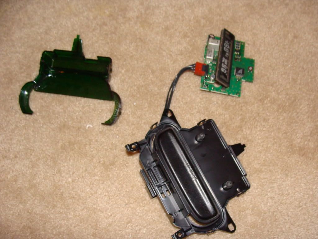
Take the green lens off, its just two clips to the housing on each side
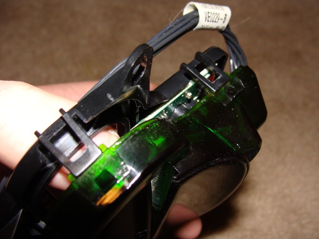
The circuit board will just lift out of black housing. You can choose to disconnect the jumper harness from the board, or leave it on there and work around the harness and housing
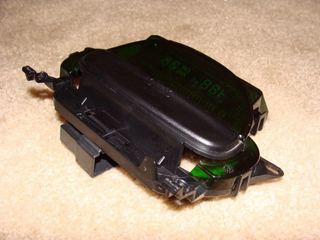
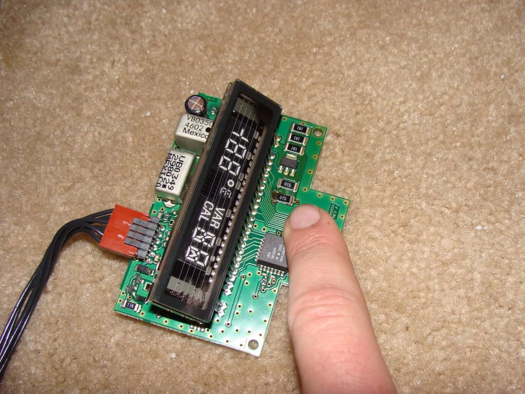
Now that its fully disassembled we will now go over the repair process.
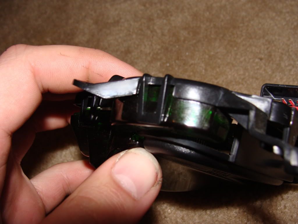
This resistor is the concern and will be the focus of my next series of pictures
From the side you can see that the resistor has popped up from the board slightly. I think this has to do with the board being suspended upside down in the truck and subjected to large temperature changes.
The repair process is actually quite simple, just a matter of heating up the solder, and nudging the resistor flat again, adding a pinch of new solder if needed.
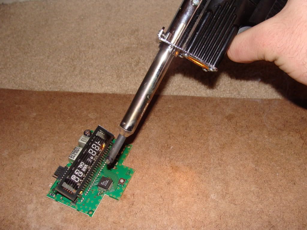
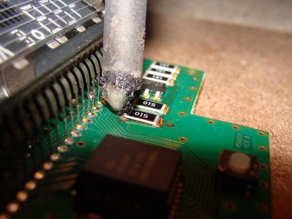
Make sure its got full solder all the way across width of the resistor and you should be good to go.
Test the display on the truck before you completely put the display and console all back together
From there work back words through the steps and reassemble the display and console.
Put it back together after successful test run and enjoy!
If you see another resistor starting to lift, you may want to give it some loving with the soldering gun, but might not be needed.
Good luck.
Before you start the process, cycle the button a couple times to make sure its not just turned off.
Tools needed:
#2 Phillips
T10 bit/driver
Soldering gun & solder
If you are not experienced with a soldering gun use caution, or let someone tackle this that knows how to do the repair safely.
I am not responsible for any damages to you or your truck, this is merely a guideline to go by, individual results may vary
Start by removing the Phillips screw located above the mirror
In the rear door, there are plastic tab that have a metal clip. (one on each side) But all you need to do is just grab the console firmly and pull straight down on it. The console will pop off, make sure you dont pull too hard or you risk damaging the wires on the display.
The wiring connector is just clipped on the display, just slide it straight right to left
Disconnect the wiring connector, and take the console to your work bench (tailgate) and prepare to disassemble it.
Next you will see the 4 T10 screws.
Once removed, you will have the entire display unit
Take the green lens off, its just two clips to the housing on each side
The circuit board will just lift out of black housing. You can choose to disconnect the jumper harness from the board, or leave it on there and work around the harness and housing
Now that its fully disassembled we will now go over the repair process.
This resistor is the concern and will be the focus of my next series of pictures
From the side you can see that the resistor has popped up from the board slightly. I think this has to do with the board being suspended upside down in the truck and subjected to large temperature changes.
The repair process is actually quite simple, just a matter of heating up the solder, and nudging the resistor flat again, adding a pinch of new solder if needed.
Make sure its got full solder all the way across width of the resistor and you should be good to go.
Test the display on the truck before you completely put the display and console all back together
From there work back words through the steps and reassemble the display and console.
Put it back together after successful test run and enjoy!
If you see another resistor starting to lift, you may want to give it some loving with the soldering gun, but might not be needed.
Good luck.
Thanks.