SD Trans Cooler install + How-To with loads of
#1
 10-05-2007, 10:34 PM


Join Date: Jan 2006
Location: Port Royal, SC
Posts: 1,292
Likes: 0
Received 0 Likes
on
0 Posts
Jeff (GK_crewchief) liked the way I did my trans cooler with the braided lines to he contacted me about a list of all the parts I used. He then asked if I would be willing to help him install it if he drove down here from Fayetteville, NC. Being the wrench-junkie I am, I couldn't refuse. Jeff got here around 2PM and we had lunch before we started. I must say that Jeff's L is very nice and kept in outstanding condition. It was going to be a pleasure to work on this Lightning. Then we got to work. I decided to take this opportunity to take a lot of pics so I could do a detailed How-To since I didn't when I did mine. Hopefully the following will assist anyone planning to do this. Here's we go...
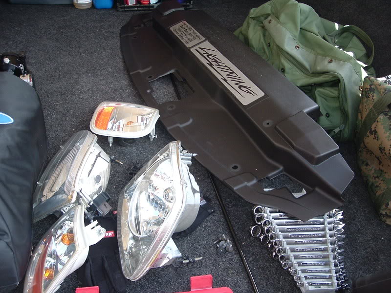
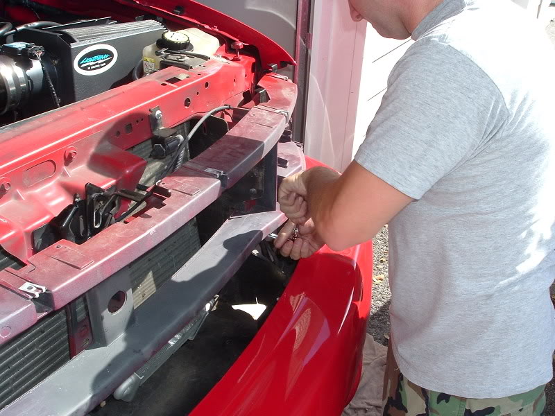
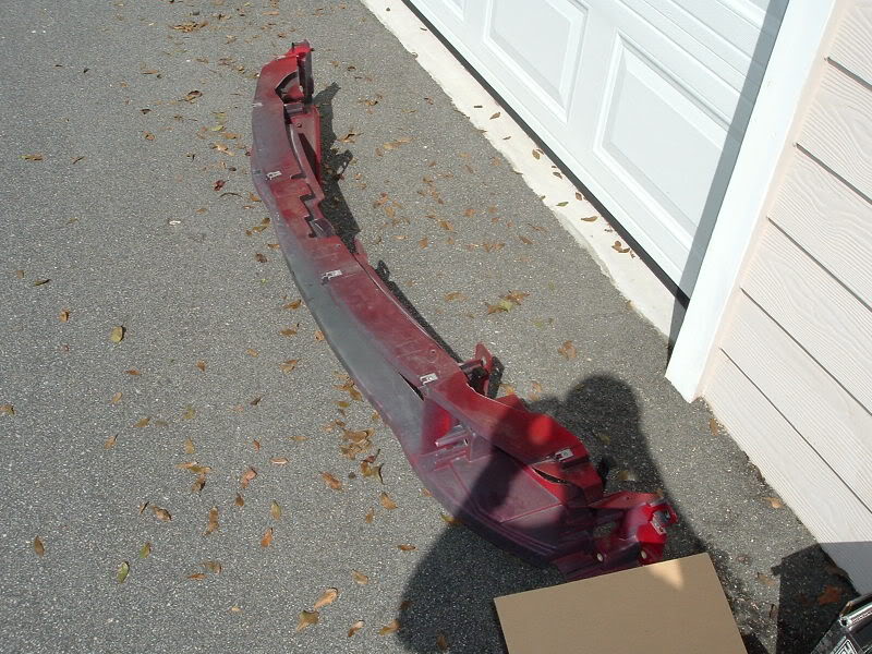
First we elevated the front end via some drive-on ramps that Jeff brought with him. Then we went to removing the headlights, corner lamps, radiator cover, the grille and the grille support.
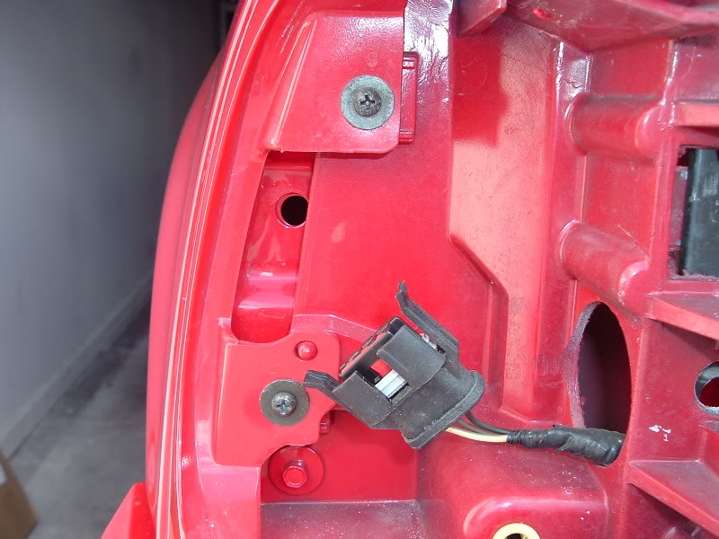
Remove the headlights by pulling up on the two taps behind each one. Then pull the headlight out and disconnect the connector. Remove the corner lamps by removing the retaining screw on the top and then pull each one out and disconnect the connector. Sorry, no pics but it's very easy.
Then we went to removing the grille...
There are 6 screws on the top and two on each side that need to be removed to get the grille off....
First we elevated the front end via some drive-on ramps that Jeff brought with him. Then we went to removing the headlights, corner lamps, radiator cover, the grille and the grille support.
Remove the headlights by pulling up on the two taps behind each one. Then pull the headlight out and disconnect the connector. Remove the corner lamps by removing the retaining screw on the top and then pull each one out and disconnect the connector. Sorry, no pics but it's very easy.
Then we went to removing the grille...
There are 6 screws on the top and two on each side that need to be removed to get the grille off....
#2
10-05-2007, 10:35 PM
Join Date: Jan 2006
Location: Port Royal, SC
Posts: 1,292
Likes: 0
Received 0 Likes
on
0 Posts
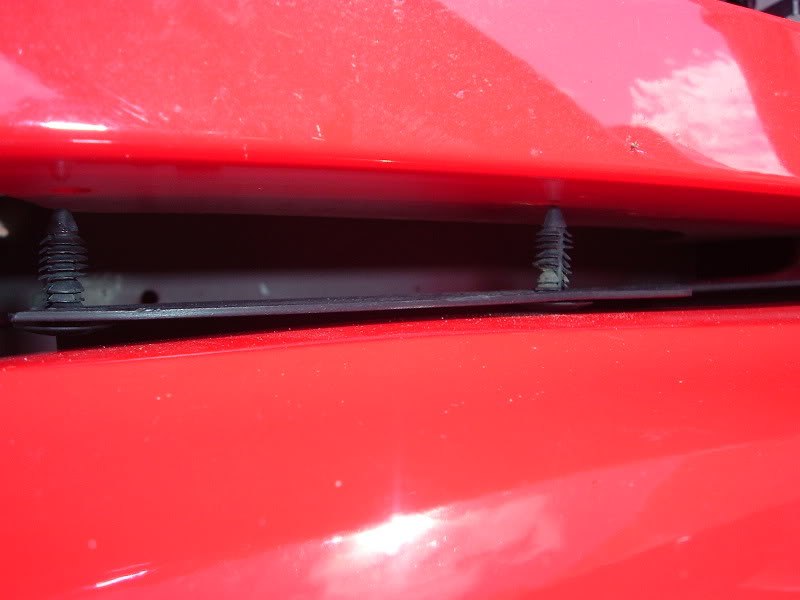
Then pry the push pins (I have no clue what the official nomenclature is) down out of the bottom of the grille on either side...
There is also two supports in the center of the grille that need to be released. It was kind of hard to get pics of them so I couldn't. You can see them through the grille and need to reach in from the top to get to them. Pull up on the clip on the bottom of each support and pull out on the grille. It will come right off.
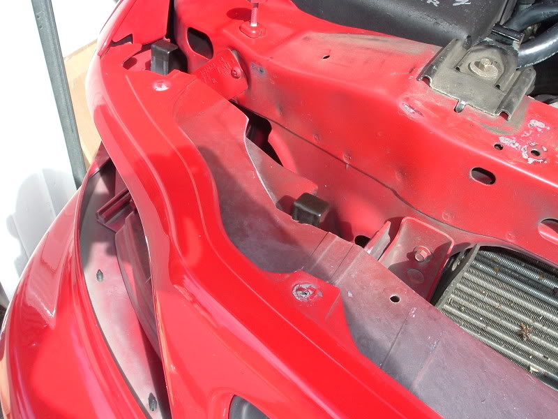
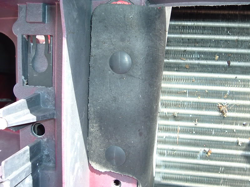
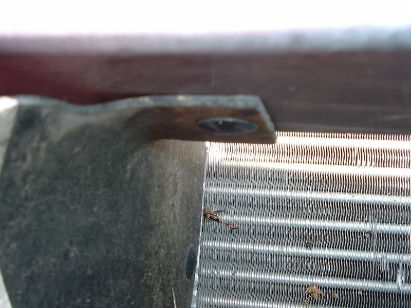
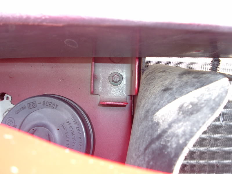
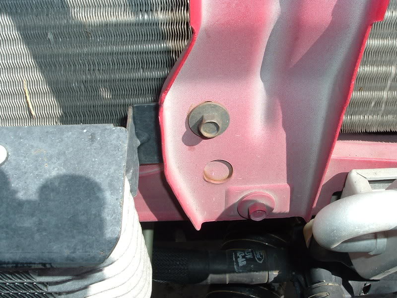
Then the grille support needs to come off. Do this by removing the two bolts in the center. Ther is one here...
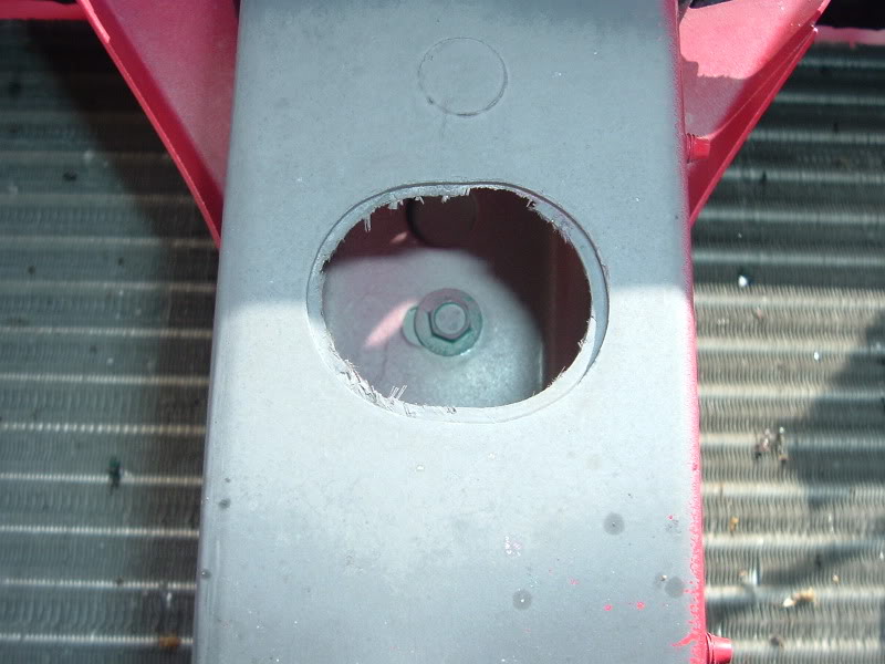
And one here...
#3
10-05-2007, 10:36 PM
Join Date: Jan 2006
Location: Port Royal, SC
Posts: 1,292
Likes: 0
Received 0 Likes
on
0 Posts
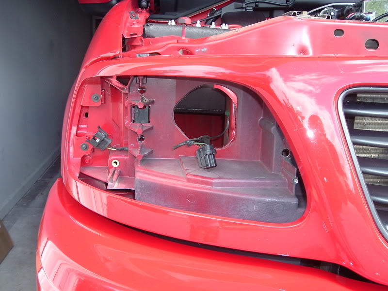
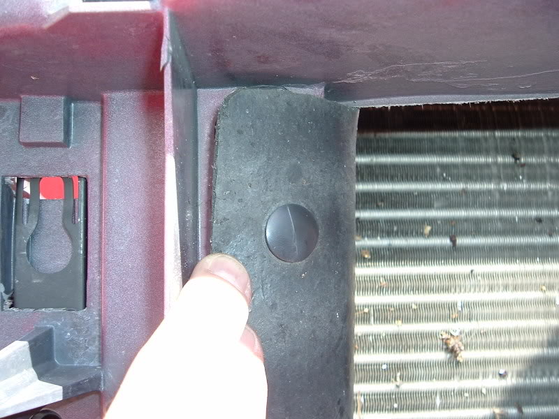
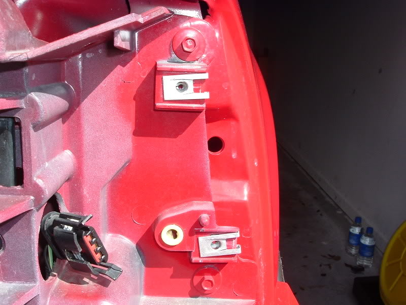
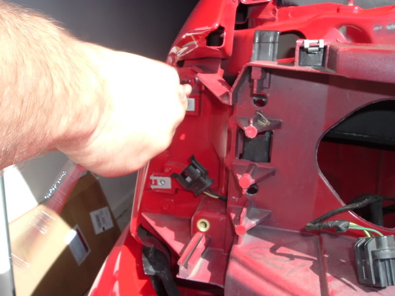
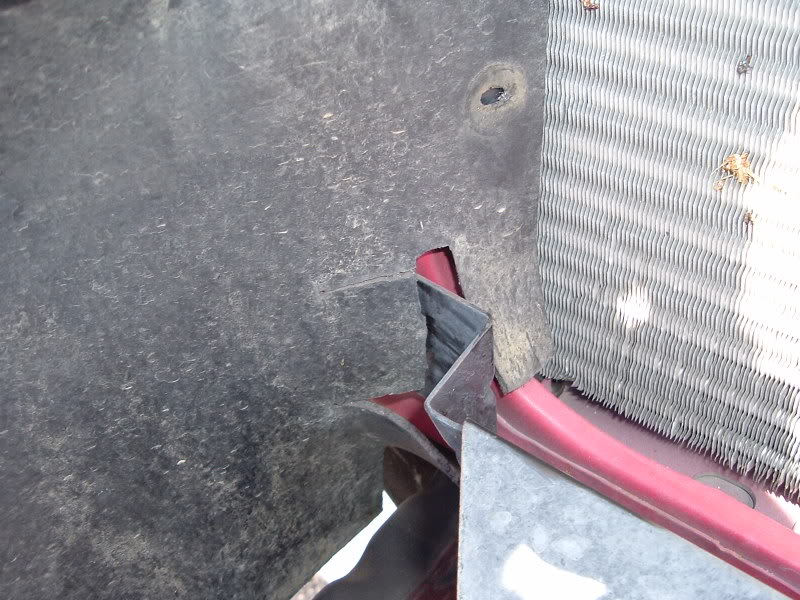
Before moving on, pry all of the push pins out that attach the splash guard to the grille support. Here are some of the locations but it's obvious where they all are when you're looking at it...
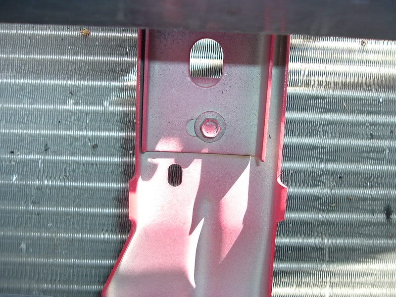
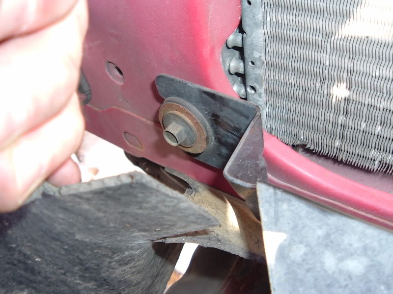
When you pull the side ones you will expose some more bolts that must be removed. There is one on the top and one on the bottom...
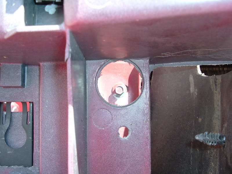
When you pull the side ones you will expose some more bolts that must be removed. There is one on the top and one on the bottom...
#4
10-05-2007, 10:37 PM
Join Date: Jan 2006
Location: Port Royal, SC
Posts: 1,292
Likes: 0
Received 0 Likes
on
0 Posts
#5
10-05-2007, 10:38 PM
Join Date: Jan 2006
Location: Port Royal, SC
Posts: 1,292
Likes: 0
Received 0 Likes
on
0 Posts
#6
10-05-2007, 10:39 PM
Join Date: Jan 2006
Location: Port Royal, SC
Posts: 1,292
Likes: 0
Received 0 Likes
on
0 Posts
#7
10-05-2007, 10:40 PM
Join Date: Jan 2006
Location: Port Royal, SC
Posts: 1,292
Likes: 0
Received 0 Likes
on
0 Posts
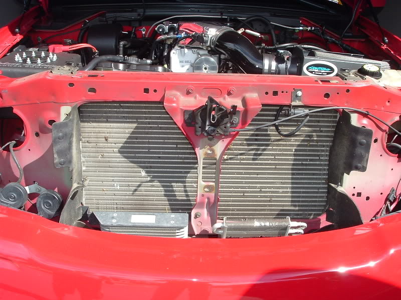
Then remove the stock cooler...
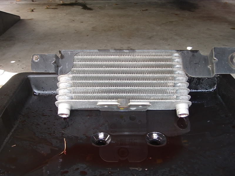
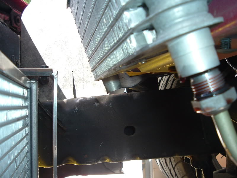
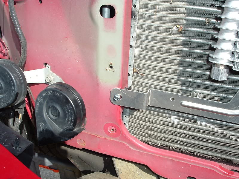
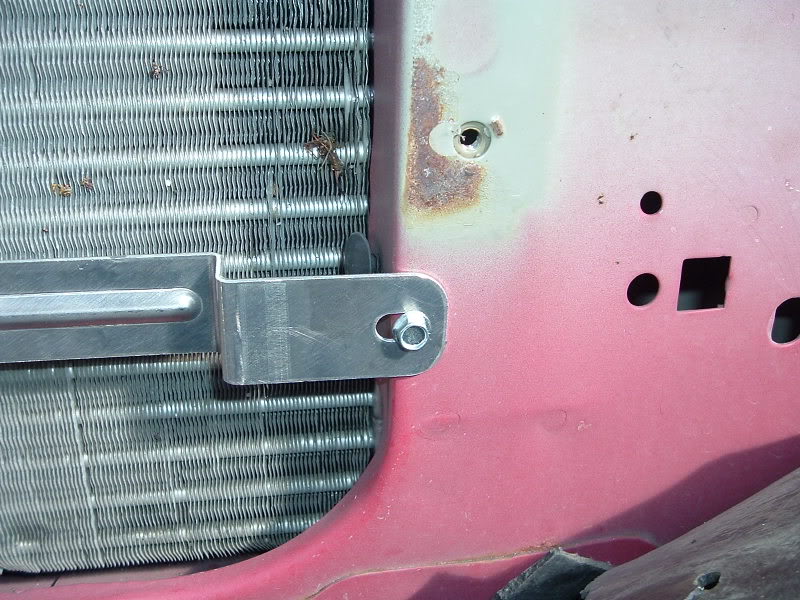
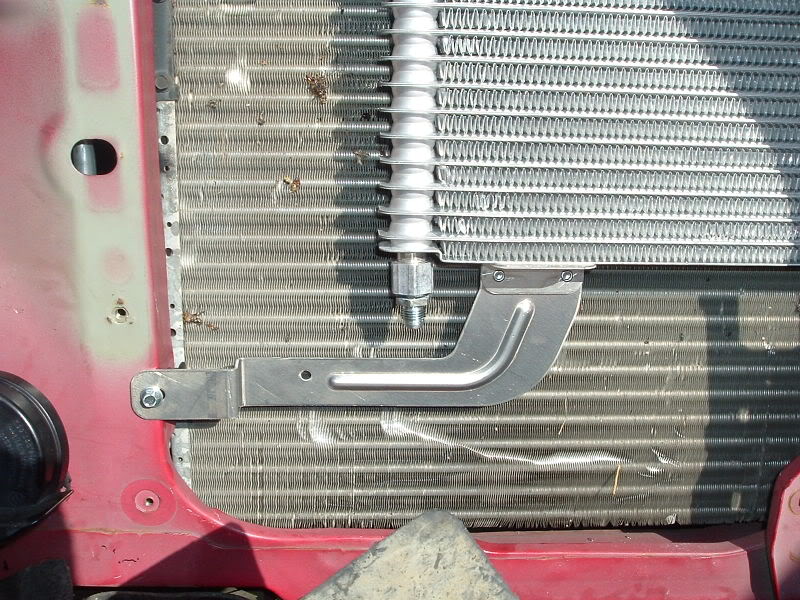
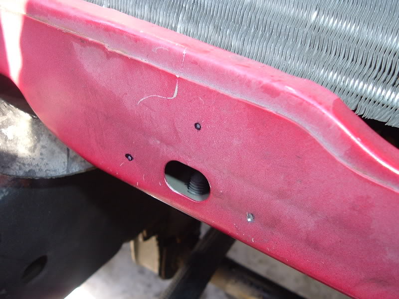
We then decided to go ahead and mount the new Ford Super-Duty Trans Cooler (Ford Part # XC3Z-7A095-CA). We carefully maneuvered the cooler behind the center hood latch support and then held it up to where we wanted to mount it. We then maked the mounting locations with a black Sharpie and drilled some pilot holes. Then I used some self-tapping screws to secure the new cooler. I went back later and installed some washers because I didn't like how the screws were almost too small for the holes...
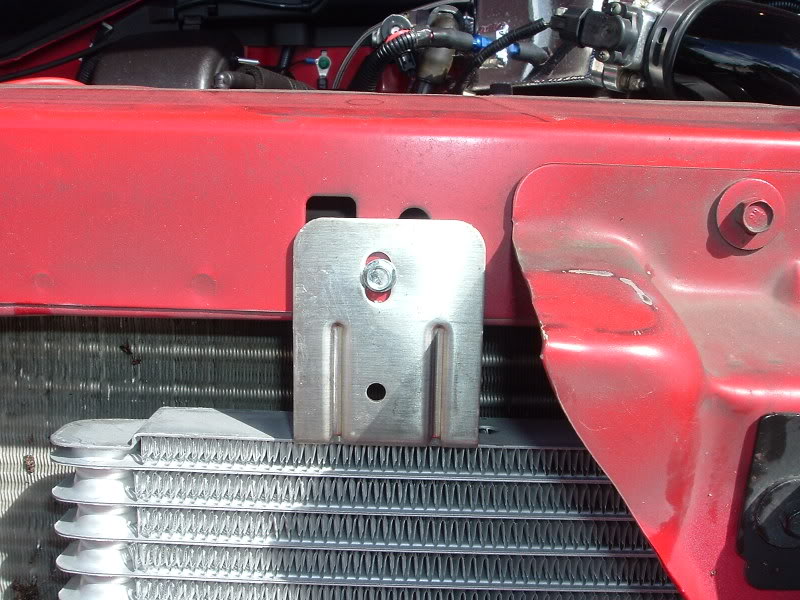
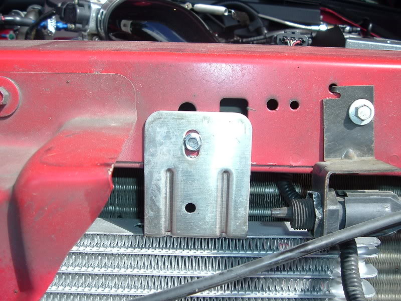
We then decided to go ahead and mount the new Ford Super-Duty Trans Cooler (Ford Part # XC3Z-7A095-CA). We carefully maneuvered the cooler behind the center hood latch support and then held it up to where we wanted to mount it. We then maked the mounting locations with a black Sharpie and drilled some pilot holes. Then I used some self-tapping screws to secure the new cooler. I went back later and installed some washers because I didn't like how the screws were almost too small for the holes...
Trending Topics
#8
10-05-2007, 10:41 PM
Join Date: Jan 2006
Location: Port Royal, SC
Posts: 1,292
Likes: 0
Received 0 Likes
on
0 Posts
#9
10-05-2007, 10:42 PM
Join Date: Jan 2006
Location: Port Royal, SC
Posts: 1,292
Likes: 0
Received 0 Likes
on
0 Posts
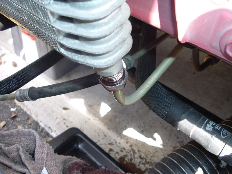
Then I used my tubing cutter and cut the hard lines...
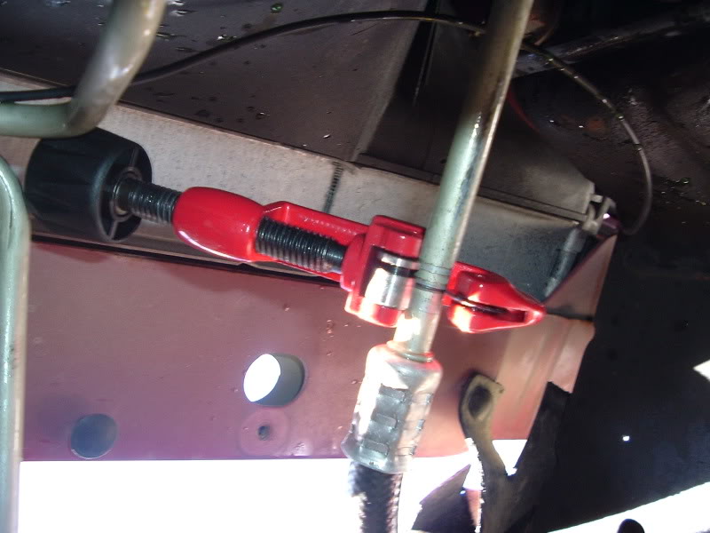
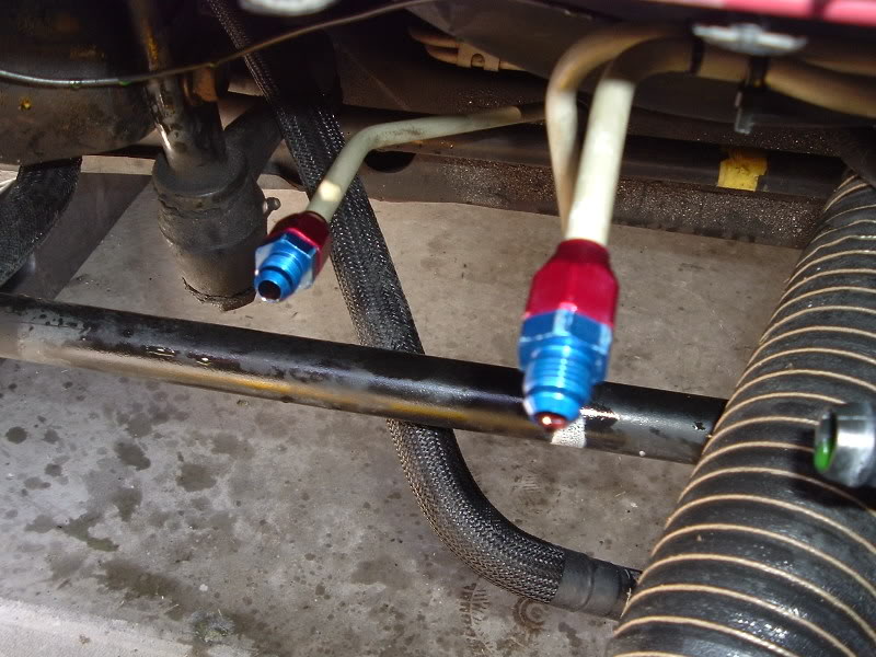
We then installed the Russell -6AN Male to 3/8" Tubing Compression Fittings (Part # RUS-639210) that Jeff brought with him. I applied some pipe-thread sealant to use as a lubricant for the compression ring and also to assist in sealing the threads of the fitting. First install the red female fitting on the tube. Then the brass compression ring. And then the blue male fitting. Press the assembly onto the tube as you begin tightening the fittings together. After a few turns and the compression ring has begun to compress on the tubing, you can let go of the fitting and focus on tightening them together until the two fittings make contact. Repeat this procedure for the other hard line and this portion is finished...
#10
10-05-2007, 10:43 PM
Join Date: Jan 2006
Location: Port Royal, SC
Posts: 1,292
Likes: 0
Received 0 Likes
on
0 Posts
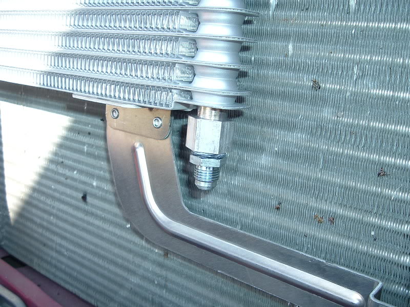
Next we installed the two Russell -6AN Male to 5/8-18" Straight Inverted Flare Fittings (Part # RUS-640380) in the cooler ports. Jeff applied some pipe thread sealant and we tightened them into place. Make sure to use a wrench to hold the cooler port when tightening the fitting as you may bend the cooler when tightening the fittings. We tightened the fittings until they were good and snug making sure not to over-tighten and possibly damage the threads of the cooler...
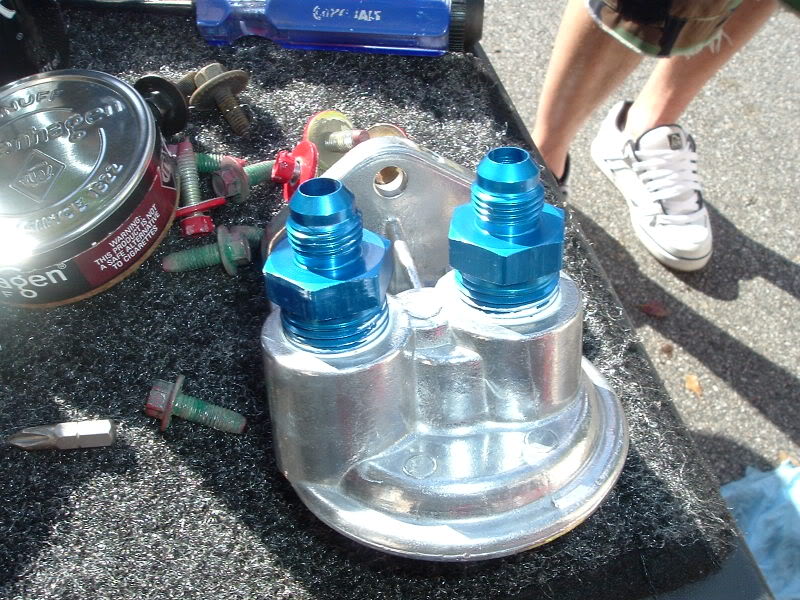
We then installed the Russell -6AN Male to 1/2" NPT Male Straight Fittings (Part # RUS-670150) into the Perma-Cool Oil Filter Mount (Part # PRM-1211). Again, we used some pipe thread sealant on the NPT threads of the fittings and tightened them down...
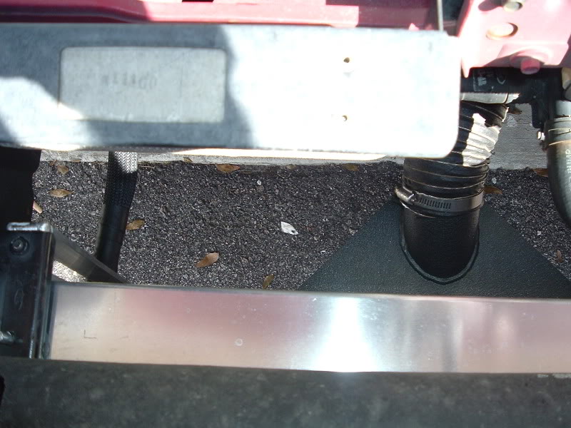
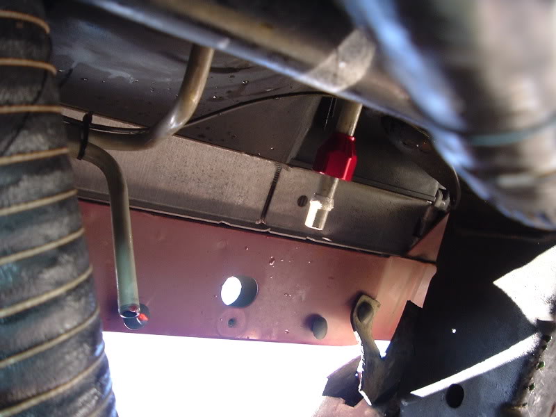
Then we installed the oil filter mount. We were going to install it in the same location I have mine (wheel well) but we decided to install it to where the filter would be behind the Heat Exchanger on the passenger side. I just made my marks with the Sharpie and drilled some pilot holes for the sheetmetal screws I used. You'll need to use a wrench to install the two outside screws because there isn't enough clearance to use a ratchet. I was able to use a ratchet for the center screw but I had to use an extension. Pics of it installed are later in this thread...
We then installed the Russell -6AN Male to 1/2" NPT Male Straight Fittings (Part # RUS-670150) into the Perma-Cool Oil Filter Mount (Part # PRM-1211). Again, we used some pipe thread sealant on the NPT threads of the fittings and tightened them down...
Then we installed the oil filter mount. We were going to install it in the same location I have mine (wheel well) but we decided to install it to where the filter would be behind the Heat Exchanger on the passenger side. I just made my marks with the Sharpie and drilled some pilot holes for the sheetmetal screws I used. You'll need to use a wrench to install the two outside screws because there isn't enough clearance to use a ratchet. I was able to use a ratchet for the center screw but I had to use an extension. Pics of it installed are later in this thread...
#11
10-05-2007, 10:44 PM
Join Date: Jan 2006
Location: Port Royal, SC
Posts: 1,292
Likes: 0
Received 0 Likes
on
0 Posts
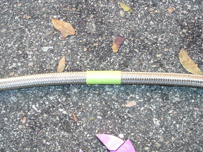
Then we went to assembling the hoses and fittings. Here is an illustration and explanation on how to apply AN fittings to braided stainless steel hose...
First wrap the hose woth some kind of tape to prevent the braid from fraying when you cut it. I used painters tape...
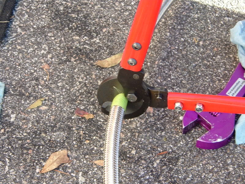
Then cut the hose in the center of the tape to you'll have the tape on both pieces you just cut. I use Summit AN Braided Stainless Steel hose cutters to cut my hoses. They cut great...
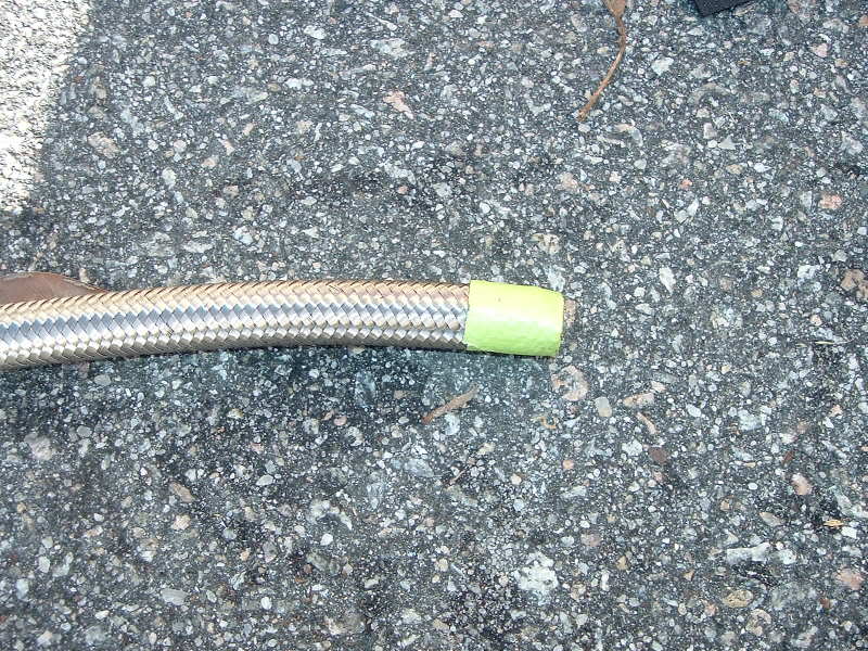
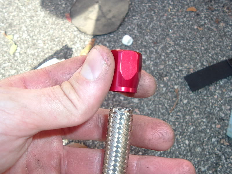
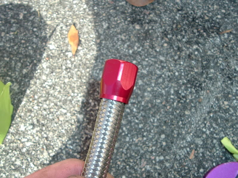
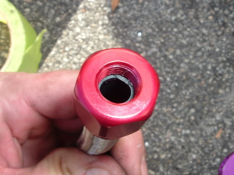
Then carefully remove the tape from the end of the hose and carefully but forcefully apply the female end (red) of the AN fitting until the hose is snug and flush with the flange inside...
First wrap the hose woth some kind of tape to prevent the braid from fraying when you cut it. I used painters tape...
Then cut the hose in the center of the tape to you'll have the tape on both pieces you just cut. I use Summit AN Braided Stainless Steel hose cutters to cut my hoses. They cut great...
Then carefully remove the tape from the end of the hose and carefully but forcefully apply the female end (red) of the AN fitting until the hose is snug and flush with the flange inside...
#12
10-05-2007, 10:46 PM
Join Date: Jan 2006
Location: Port Royal, SC
Posts: 1,292
Likes: 0
Received 0 Likes
on
0 Posts
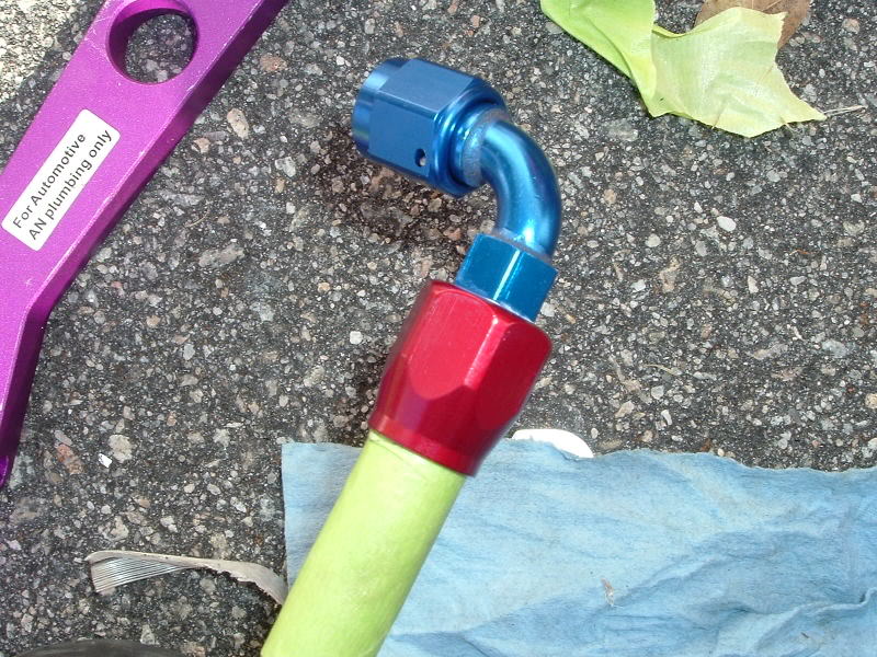
Then apply some lubricant to the male end (blue) of the AN fitting. In this case I used good ol pipe thread sealant...
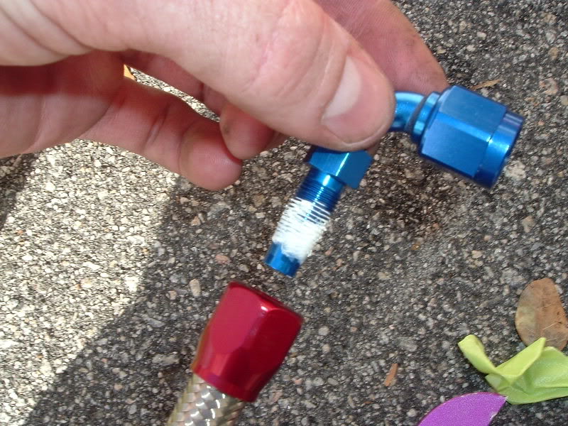
Then push the male end of the AN fitting into the female end until the male fitting penetrates the hose. I also marked the fitting in relation to the hose with some painters tape to ensure the fitting wasn't pushing the hose out...
#13
10-05-2007, 10:47 PM
Join Date: Jan 2006
Location: Port Royal, SC
Posts: 1,292
Likes: 0
Received 0 Likes
on
0 Posts
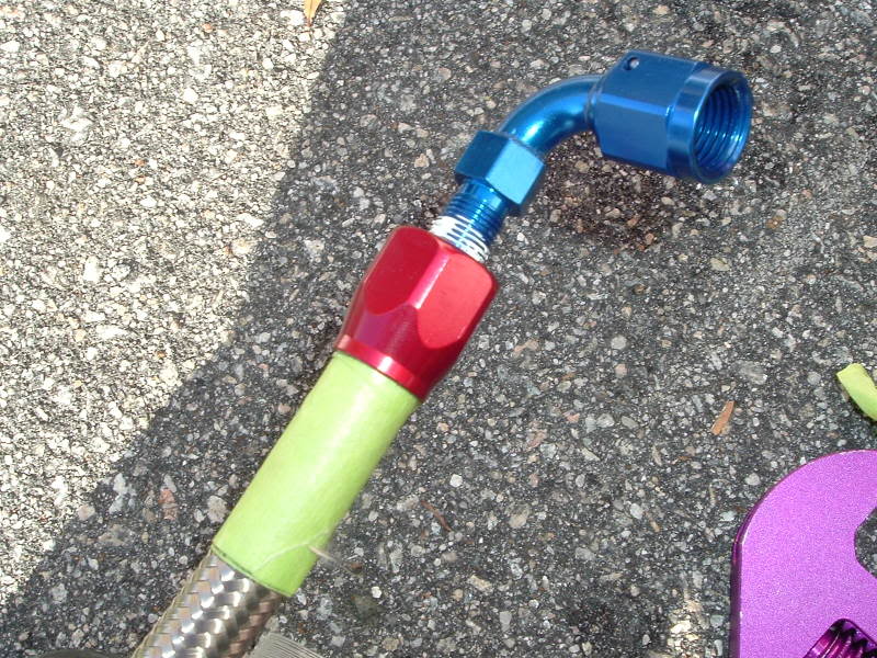
Then begin to tighten the fittings together. Every couple of turns check the tape and make sure the hose isn't pushing out of the fitting. This doesn't happen very often but it's possible...
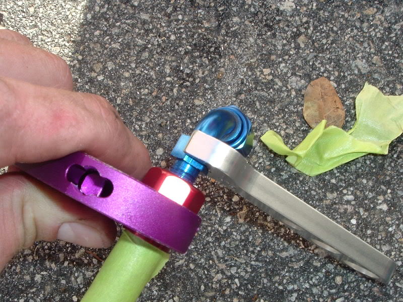
Keep tightening the fittings together until they are fully seated with one another. That's it! Remove the tape and move on to the next step...
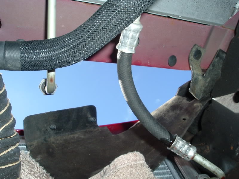
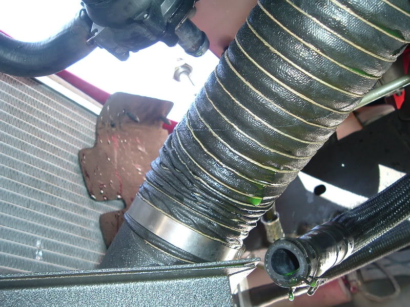
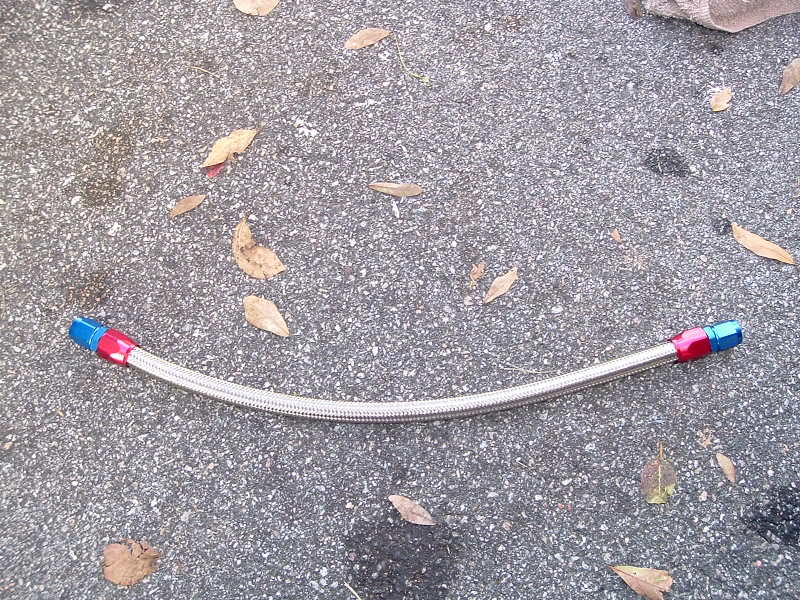
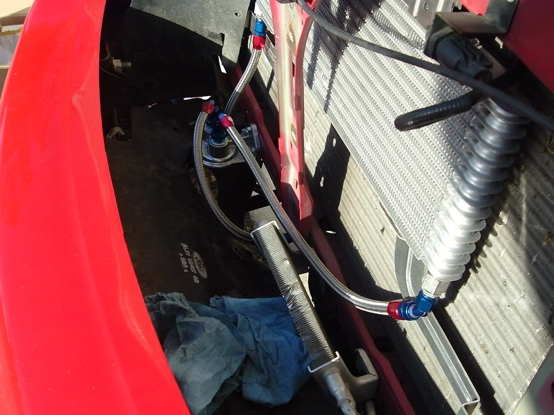
We decided to install the return line from the cooler to the return hard line first. We did this by using a section of Russell -6AN Braided Stainless Steel Proflex Hose (Part # RUS-632060) and two Russell -6AN Hose to Female -6AN Straight Hose End Fittings (Part # RUS-610020). I installed one of the hose end fitting on the hose using the procedures mentioned earlier. Then I installed the hose and fitting to the cooler fitting and measure the distance from the cooler fitting to the return line compression fitting. I did this by feeding the hose down to the fitting and marking it with tape. I then removed the hose from the cooler and cut it on the tape. I installed the other fitting and then installed the assembly on the truck...
Keep tightening the fittings together until they are fully seated with one another. That's it! Remove the tape and move on to the next step...
We decided to install the return line from the cooler to the return hard line first. We did this by using a section of Russell -6AN Braided Stainless Steel Proflex Hose (Part # RUS-632060) and two Russell -6AN Hose to Female -6AN Straight Hose End Fittings (Part # RUS-610020). I installed one of the hose end fitting on the hose using the procedures mentioned earlier. Then I installed the hose and fitting to the cooler fitting and measure the distance from the cooler fitting to the return line compression fitting. I did this by feeding the hose down to the fitting and marking it with tape. I then removed the hose from the cooler and cut it on the tape. I installed the other fitting and then installed the assembly on the truck...
#14
10-05-2007, 10:48 PM
Join Date: Jan 2006
Location: Port Royal, SC
Posts: 1,292
Likes: 0
Received 0 Likes
on
0 Posts
We decided to install the hose from the feed line to the inlet port of the filter mount next. It's important to install the filter before the cooler so that in the event of a transmission failure, the debris will get caught by the filter and not contaminate the cooler.
We used another section of Russell -6AN Proflex Hose. We also used one Russell -6AN Hose to Female -6AN 90 Degree Hose End Fitting (Part # RUS-610160) and one Russell -6AN Hose to Female -6AN 45 Degree Hose End Fitting (Part # RUS-613090). I used the same procedures mentioned earlier to assemble, measure and install this hose...
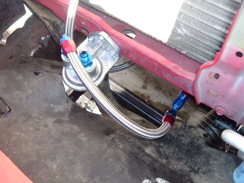
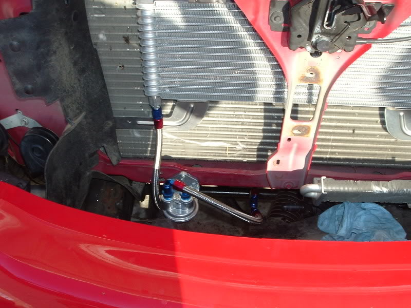
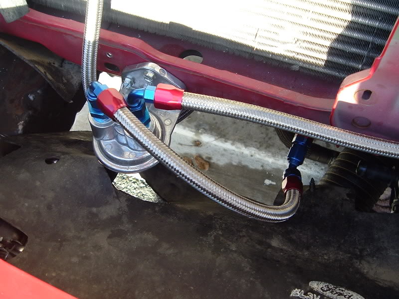
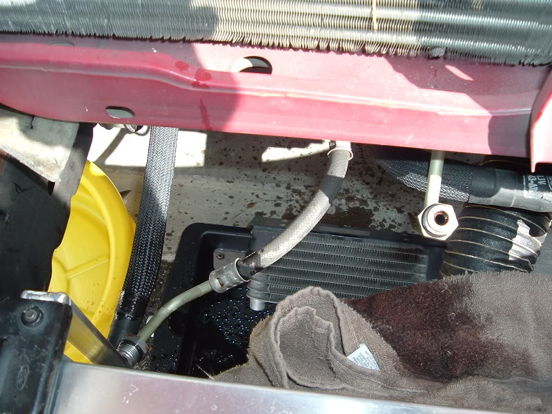
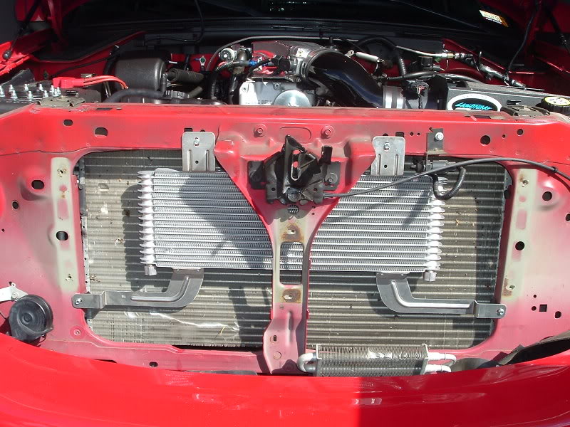
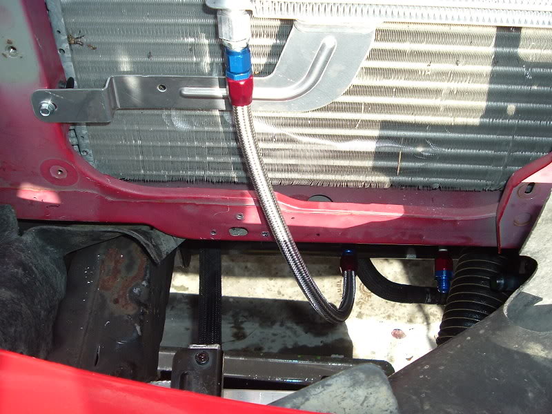
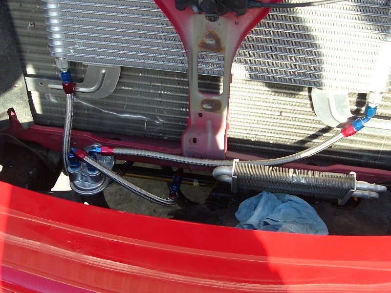
Then we used another section of Russell -6AN Proflex Hose, another Russell -6AN 90 Degree Fitting and another Russell -6AN 45 Degree Fitting to assemble and install the hose from the outlet port of the filter mount to the drivers side of the cooler. Here's how it all looked once we finshed the plumbing...
We used another section of Russell -6AN Proflex Hose. We also used one Russell -6AN Hose to Female -6AN 90 Degree Hose End Fitting (Part # RUS-610160) and one Russell -6AN Hose to Female -6AN 45 Degree Hose End Fitting (Part # RUS-613090). I used the same procedures mentioned earlier to assemble, measure and install this hose...
Then we used another section of Russell -6AN Proflex Hose, another Russell -6AN 90 Degree Fitting and another Russell -6AN 45 Degree Fitting to assemble and install the hose from the outlet port of the filter mount to the drivers side of the cooler. Here's how it all looked once we finshed the plumbing...
#15
10-05-2007, 10:49 PM
Join Date: Jan 2006
Location: Port Royal, SC
Posts: 1,292
Likes: 0
Received 0 Likes
on
0 Posts