Steering Stabilizer DIY Installation
#1
 12-02-2009, 02:08 AM


Join Date: Jul 2008
Location: SEATTLE, WASHINGTON
Posts: 29
Likes: 0
Received 0 Likes
on
0 Posts
Steering Stabilizer DIY Installation
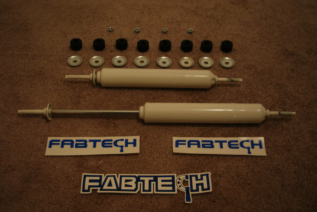
I ordered the Fabtech Dual Steering Stabilizers from Top Gun Customz website. In their system it is part #Fabtech_FTS8009. It came out be be $177.00 shipped to my door. Pretty good deal if you ask me. It arrived about 6 days in a 14lb box. Inside the box this is what I found:

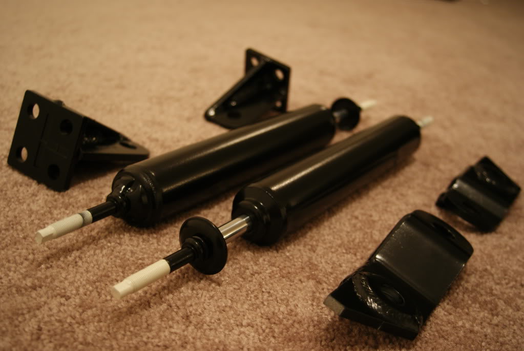
Here is the shocks and their components. The picture does not include the Backets and Hardware:
So of course I need to get these to blend with the truck a little better. On came prep for Priming and Painting:
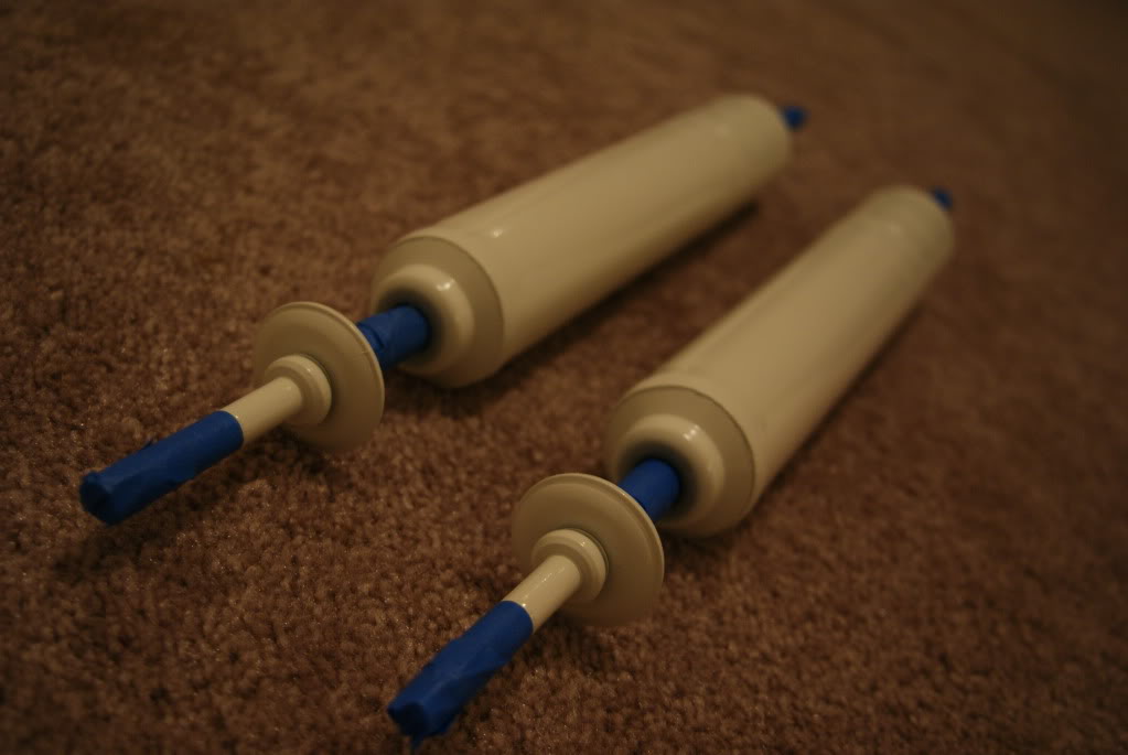
Here is all the components of the kit primed and hanging on my painting contraption:
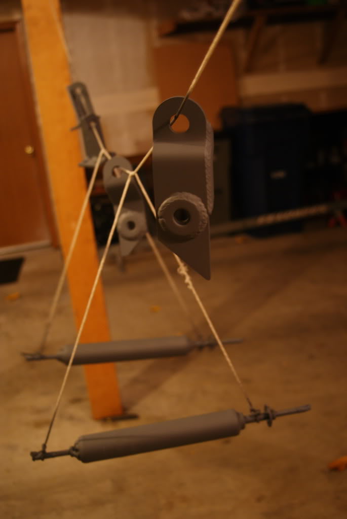
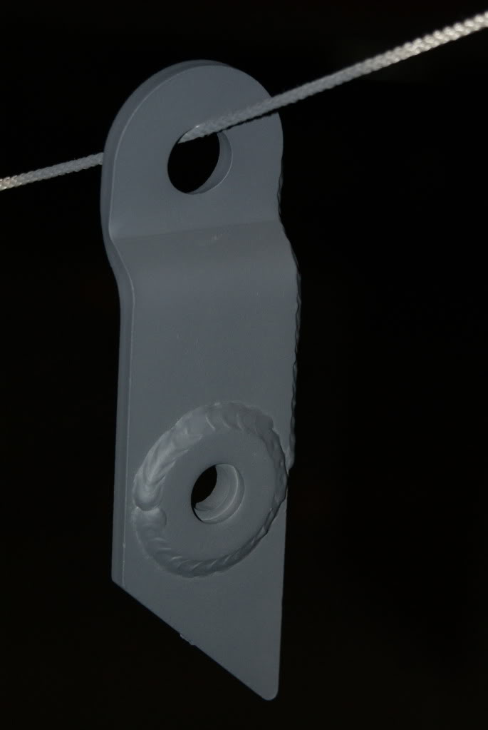
Here is a close up of the Passenger Side Rack & Pinion Bracket and a Tie-Rod Bracket all Primed:

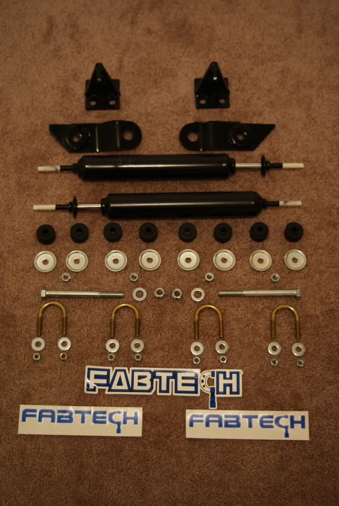
Here is the Finished Product:
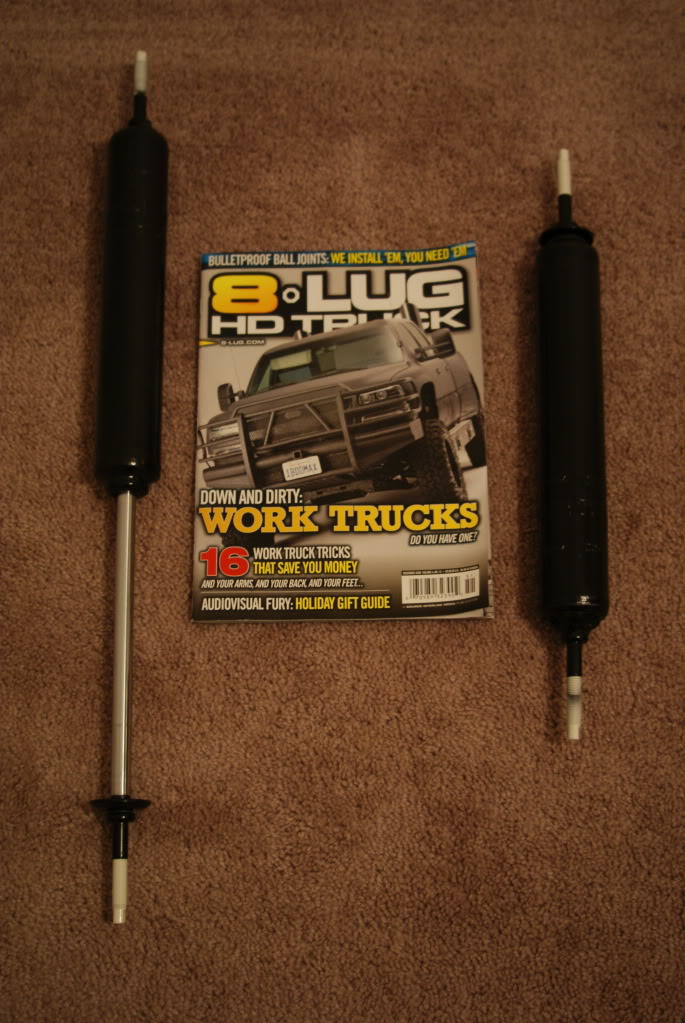
And Now since everything is the way I wanted here is the Big Picture and also a comparison of fully extended and fully compressed:
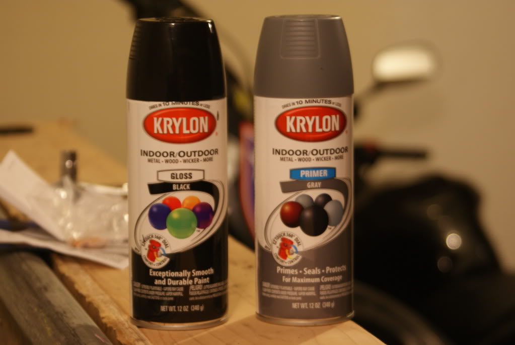
In case you were wondering here is my weapons of choice:
OK...So now onto the tech. This install took my about an hour to complete, and that included time to eat a sandwich and organize all of the tools (cause I hate seeing them just scattered all over). While still being able to take my time in general. The only tools you will need are:
Socket Wrench
Torque Wrench
Adjustable Wrench or Pliers
19mm socket
13mm socket
14mm socket
Thats about it unless you have stock rims. I could see this being an issue with access to the Tie-Rod. But all you would need to do is remove the wheels/tires.
All this information is covered in the instructions you will get, but it is nice to know what you will be stepping into.
So who would have known a Tow-Hook has more than one very helpful use:
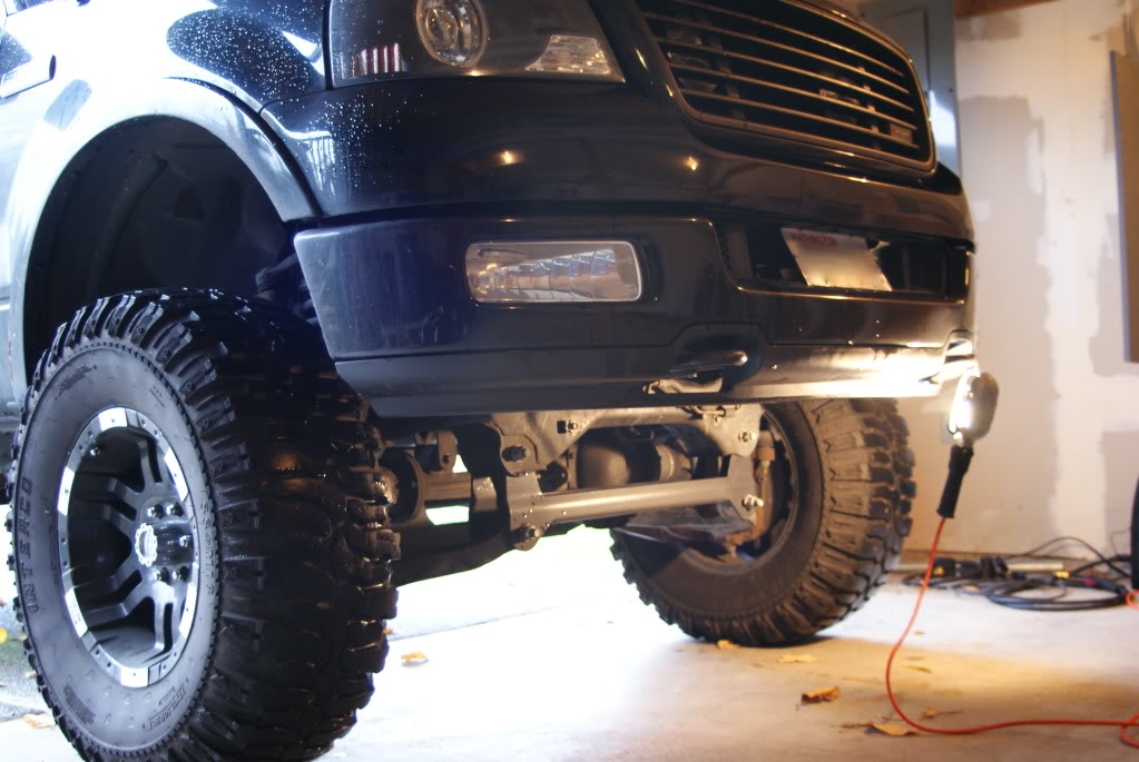
With this helpful light you can see the Rack & Pinion Steering system. The Driver Side Bolt is on the bottom side of this picture (sorry for the mess down there)
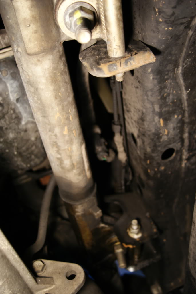
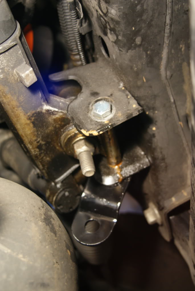
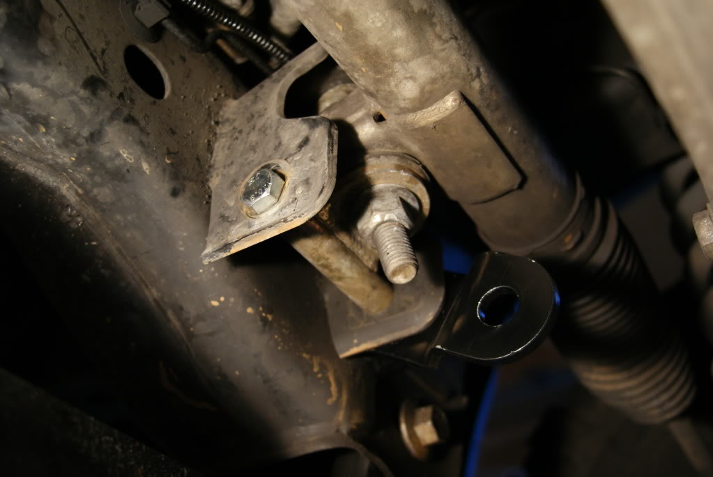
Starting with the Drivers Side Bolt you will need two 19mm socket/wrench. Replace the stock bolt with the new 12mm x 130mm bolt provided by the kit. While removing the stock bolt you can push in the new bolt in right behind it. Once the bolt is though grab the bracket #FT30077. On the bracket there is a washer welded on one side. The side with the washer will go against the frame. The angled cut on the bracket will sit flush with the vertical side of the frame/crossmember. Slide on the also newly supplied washer and nut, then torque to 70 ft lbs. Here is the Driver Side Bolt from an underside view with the bracket and also a view from the side looking in:
Now in the instructions it states that you will have to cut out about 1 inch of the passenger side bracket. I mock'd up the steering before installing this side and I didn't see any clearance issues. So I went on with the install and all turned out well. But you may want to check before you install the passenger side just to be sure.
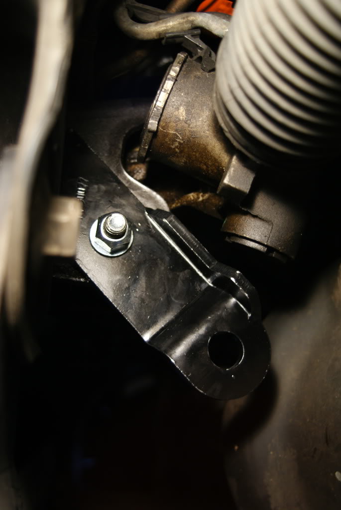
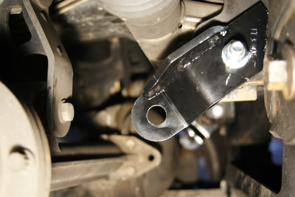
Once you have checked for clearance issues just follow the same steps for the drivers side but now with Bracket #FT30084. Once again the side with the washer welded to it will be going against the frame, and the angle cut on the bracket will sit flush vertically against the frame also. Torque to 70 ft lbs. Here are some pictures of the Passenger Side bolt with Bracket from the underside view and also side view:
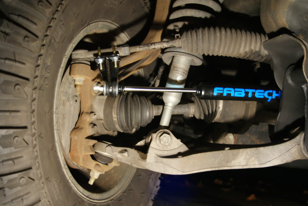
Now to the Tie-Rod Brackets you will need a 13mm socket wrench or regular wrench. Use the two provided U-bolts to secure the bracket on with the Tie-Rod using the provided washers and nuts. The tab with the whole in it will be facing towards the front of the truck. Torque these to 25ft lbs. There is a flat spot on the bottom of the Tie-Rod to help hold the bracket in place a little. Here is what it looks like completed (don't rag on my rusty spindles. I beat myself up enough already)
<a href="http://s621.photobucket.com/albums/tt299/Buzzshots16/Steering%20Stabilizers/?action=view¤t=DSC05682.jpg" target="_blank"><img src="http://i621.photobucket.com/albums/tt299/Buzzshots16/Steering%20Stabilizers/DSC05682.jpg" border="0" alt="Tie Rod Bracket"></a>
Once both sides are done we can move on to putting the stabilizers in place. you will need a 14mm wrench (sockets to not work on this part) and also an adjustable wrench or a pair or pliers to secure the studs while you tighten the bolt. The key to this is getting the bushings to compress enough to catch a thread on the studs. Once you use to leverage to catch the nut on the threads you just hold the end of the stud and tighten the bolt with the wrench. You will need to torque these nuts to 25ft lbs. Once you have the stabilizers in place and tightened on. Dress it up a little and your about set to go:
I need to get my frame painted! Or at least my crossmember and all its components.
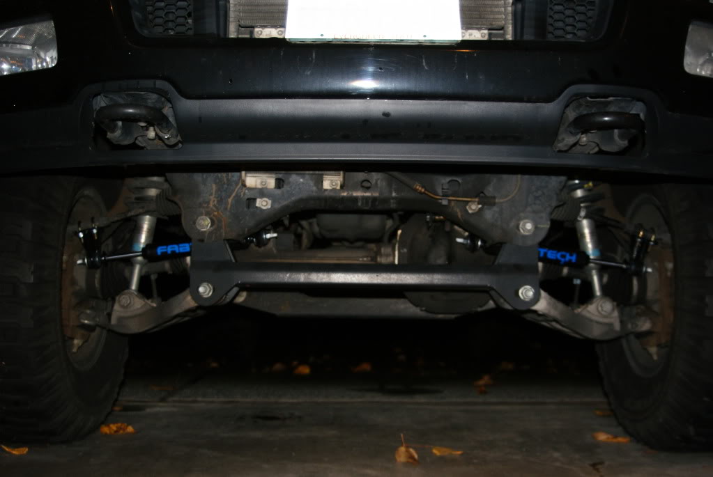
Anyways.....After standing back to admire for a second come back and have a buddy or your girl cycle through the steering while you watch for any clearance issues. You also don't want the stabilizers to fully extend or fully compress curing the cycle through the steering. After you have checked for steering issues and pass, then you are set to go. Just tighten everything up in a couple days of driving. Or one really long day of driving. Here is pics of my stabilizers fully extended and also fully compressed. I was A-OK.
I will try to get a better overall shot with them installed and the whole truck. I am just waiting for a day not to rain here is Washington. But I have gotten alot of compliments from guys in cars who will see the bright blue from the fabtech stickers when their lights hit them I guess. They have no clue that they are steering stabilizers they just think it looks good. But ohh well the air must be a little different down there! I hope you all either found this useful or at least entertaining to look through and read. If you have any questions at all I am more than willing to answer. It is a pretty straight forward install, not very difficult at all. Thanks for looking through. Buzz.
Here is the shocks and their components. The picture does not include the Backets and Hardware:
So of course I need to get these to blend with the truck a little better. On came prep for Priming and Painting:
Here is all the components of the kit primed and hanging on my painting contraption:
Here is a close up of the Passenger Side Rack & Pinion Bracket and a Tie-Rod Bracket all Primed:
Here is the Finished Product:
And Now since everything is the way I wanted here is the Big Picture and also a comparison of fully extended and fully compressed:
In case you were wondering here is my weapons of choice:
OK...So now onto the tech. This install took my about an hour to complete, and that included time to eat a sandwich and organize all of the tools (cause I hate seeing them just scattered all over). While still being able to take my time in general. The only tools you will need are:
Socket Wrench
Torque Wrench
Adjustable Wrench or Pliers
19mm socket
13mm socket
14mm socket
Thats about it unless you have stock rims. I could see this being an issue with access to the Tie-Rod. But all you would need to do is remove the wheels/tires.
All this information is covered in the instructions you will get, but it is nice to know what you will be stepping into.
So who would have known a Tow-Hook has more than one very helpful use:
With this helpful light you can see the Rack & Pinion Steering system. The Driver Side Bolt is on the bottom side of this picture (sorry for the mess down there)
Starting with the Drivers Side Bolt you will need two 19mm socket/wrench. Replace the stock bolt with the new 12mm x 130mm bolt provided by the kit. While removing the stock bolt you can push in the new bolt in right behind it. Once the bolt is though grab the bracket #FT30077. On the bracket there is a washer welded on one side. The side with the washer will go against the frame. The angled cut on the bracket will sit flush with the vertical side of the frame/crossmember. Slide on the also newly supplied washer and nut, then torque to 70 ft lbs. Here is the Driver Side Bolt from an underside view with the bracket and also a view from the side looking in:
Now in the instructions it states that you will have to cut out about 1 inch of the passenger side bracket. I mock'd up the steering before installing this side and I didn't see any clearance issues. So I went on with the install and all turned out well. But you may want to check before you install the passenger side just to be sure.
Once you have checked for clearance issues just follow the same steps for the drivers side but now with Bracket #FT30084. Once again the side with the washer welded to it will be going against the frame, and the angle cut on the bracket will sit flush vertically against the frame also. Torque to 70 ft lbs. Here are some pictures of the Passenger Side bolt with Bracket from the underside view and also side view:
Now to the Tie-Rod Brackets you will need a 13mm socket wrench or regular wrench. Use the two provided U-bolts to secure the bracket on with the Tie-Rod using the provided washers and nuts. The tab with the whole in it will be facing towards the front of the truck. Torque these to 25ft lbs. There is a flat spot on the bottom of the Tie-Rod to help hold the bracket in place a little. Here is what it looks like completed (don't rag on my rusty spindles. I beat myself up enough already)
<a href="http://s621.photobucket.com/albums/tt299/Buzzshots16/Steering%20Stabilizers/?action=view¤t=DSC05682.jpg" target="_blank"><img src="http://i621.photobucket.com/albums/tt299/Buzzshots16/Steering%20Stabilizers/DSC05682.jpg" border="0" alt="Tie Rod Bracket"></a>
Once both sides are done we can move on to putting the stabilizers in place. you will need a 14mm wrench (sockets to not work on this part) and also an adjustable wrench or a pair or pliers to secure the studs while you tighten the bolt. The key to this is getting the bushings to compress enough to catch a thread on the studs. Once you use to leverage to catch the nut on the threads you just hold the end of the stud and tighten the bolt with the wrench. You will need to torque these nuts to 25ft lbs. Once you have the stabilizers in place and tightened on. Dress it up a little and your about set to go:
I need to get my frame painted! Or at least my crossmember and all its components.
Anyways.....After standing back to admire for a second come back and have a buddy or your girl cycle through the steering while you watch for any clearance issues. You also don't want the stabilizers to fully extend or fully compress curing the cycle through the steering. After you have checked for steering issues and pass, then you are set to go. Just tighten everything up in a couple days of driving. Or one really long day of driving. Here is pics of my stabilizers fully extended and also fully compressed. I was A-OK.
I will try to get a better overall shot with them installed and the whole truck. I am just waiting for a day not to rain here is Washington. But I have gotten alot of compliments from guys in cars who will see the bright blue from the fabtech stickers when their lights hit them I guess. They have no clue that they are steering stabilizers they just think it looks good. But ohh well the air must be a little different down there! I hope you all either found this useful or at least entertaining to look through and read. If you have any questions at all I am more than willing to answer. It is a pretty straight forward install, not very difficult at all. Thanks for looking through. Buzz.
Last edited by Bluejay; 12-31-2009 at 12:05 PM.
#2
12-02-2009, 10:25 AM

Senior Member
Join Date: Nov 2007
Location: Northwest IN
Posts: 267
Likes: 0
Received 0 Likes
on
0 Posts
#3
12-02-2009, 01:09 PM
Join Date: Jul 2008
Location: SEATTLE, WASHINGTON
Posts: 29
Likes: 0
Received 0 Likes
on
0 Posts
Thanks Firstdate. Im pretty happy with the way they turned out. Also I do notice a big difference in stability. It took away the little shake that I had in the steering wheel while on the freeway, and also made a much smoother ride goinig over grooves, construction, and damn sewers. And my favorite is that it does make turning the steering wheel a little bit stiffer. It actually feels like I'm pushing big rubbers now instead of being able to crank the wheel around with my pinky. Not saying its hard to push now by any means, it just feels tougher if that makes sense.
Just an FYI also the Kit online and also in the instructions states that this kit can only be used with a truck that has a Fabtech lift installed. The main reason I did this write-up is so that you can see that it uses all factory parts. Nothing involved in the installation was a part that comes on a Fabtech lift kit.
Thanks again for the compliment.
#4
12-02-2009, 07:20 PM


#5
12-02-2009, 08:59 PM
Join Date: Jul 2008
Location: SEATTLE, WASHINGTON
Posts: 29
Likes: 0
Received 0 Likes
on
0 Posts

#7
12-04-2009, 01:12 PM
Join Date: Jul 2008
Location: SEATTLE, WASHINGTON
Posts: 29
Likes: 0
Received 0 Likes
on
0 Posts
Trending Topics
#8
12-04-2009, 01:29 PM

Senior Member
Join Date: Jun 2006
Location: SE TX
Posts: 1,605
Likes: 0
Received 0 Likes
on
0 Posts
#9
12-04-2009, 04:21 PM

Senior Member
Join Date: Sep 2006
Location: Virginia Beach
Posts: 1,879
Likes: 0
Received 0 Likes
on
0 Posts
#10
12-04-2009, 06:11 PM
Join Date: Jul 2008
Location: SEATTLE, WASHINGTON
Posts: 29
Likes: 0
Received 0 Likes
on
0 Posts
I am actually debating this right now in the Articles & How To's. The post was moved there. I measured out the length of the shock while compressed (14") and I would think that as long as you have about 14 inches on the side your wheel is turned in at full crank then you shouldnt run into any problems. As least that I can think of. Its hard for me to visualize it or take measurements when I dont have a stock set-up. But take a peek over there, maybe do some measuring from the points I gave on the horrible drawing that is over there. haha. You will see what I mean. Also I was going to measure the brackets tonight to make sure it wouldnt come in contact with the LCA. If everything clears I would say you can run it. I will post up measurements when I get home a little later. Thanks for the compliment by the way.
#11
12-04-2009, 06:18 PM
Join Date: Jul 2008
Location: SEATTLE, WASHINGTON
Posts: 29
Likes: 0
Received 0 Likes
on
0 Posts
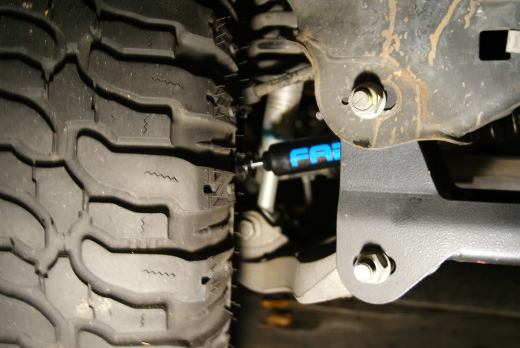
This is actually how I originally planned on running these. After I installed all the brackets I moc'd it up with the shock body on the outside. I should have taken a pic. My bad. But anyways It just didnt give the look I wanted. I like that when you look at it dead on you can see fab on one side and tech on the other. Unless I am turning that is. I had nothing against them mounted the other way, it still looks great. I just think it looks a little sleeker this way for me, plus I like seeing the shafts and its cool that when turning you can see that they are doing work since more or less shaft shows. But take a peek at the thread in the Articles & How To's section I posted up a picture there of how much clearance I have currently between the dampener and the front shock while fully turned. You can see that there should not be any clearance issues with the shock body mounted outside instead of in.


#14
12-31-2009, 01:27 AM

Join Date: May 2006
Location: High Plains of West Texas
Posts: 4,391
Likes: 0
Received 0 Likes
on
0 Posts
#15
12-31-2009, 11:52 AM
