How to- Interior LEDs
#1
 02-04-2010, 11:06 PM


Complete interior LED swap for 2004-2008 F150
Thanks to XPerties and Fabian06SC for your amazing work on being pioneers for the 3mm LED switch swap and the LED cluster swap.
I hope this helps a lot of people by combining everything into one tutorial.
This whole process took me about 10 hours, of course that was with doing all of the research I included here, re-doing the cluster now for the 4th time , fighting with the driver's side window control because of no diagram and not realizing that the driver's window switch is different the then the rest in that control as outlined in the the diagrams included, and other things going wrong.
If I did it again with the information, and with little experience, in this write-up I did I would say it should take no more then 4-5 hours.
I sadly don't have pictures for everything tonight but will have them tomorrow.
Well here's something I know everyone has been looking for. I will add all of the pictures by the end of the night, I just wanted to get it up. So please tell me if there are any errors or things that don't make sense. And of course feel free to ask any and all questions. I will eventually be adding a similar way of doing it like Fabian06SC's except with different LEDs because I feel that it is too bright doing it this way, as I have two the way he did it one with wide angle and one with narrow LEDs.
Supplies needed (With suggestion of where to buy everything, quantity, and what it’s for.):
1- 3mm LEDs (color of your choice) x 6-13 depending on amount of switches by cigarette lighter, amount of doors, and if you want to do the red blinking anti-theft light, buy 50 (for doors) Link
2- 1206 SMD LEDs (color of your choice) x 8* (for doors unless planning on using 3mm for exact match.) Link
3- PLCC-2 LEDs (color of your choice) x 20 for 4wd or 18 for 2wd, don't remember if I counted the steering wheel controls * (for HVAC and headlight switch) Link
4- 212 LED x1 (for dome light) Link
5- 194 LED x 2 (for map lights) Link
(This includes two. *The 194 bulbs will also work for license plate lights.*)
6- 470 ohm 1/4 watt resistor x 4 Link
Always buy extra in case one does not work or you mess up for the ones with an * next to their quantities.
Tools needed:
1- Lots of different size flathead screwdrivers
2- #1 or #2 Philips screwdrivers
3- T10, T15, and T20 Torx screwdrivers
4- Small needlenose pliers
5- Small wire cutters
6- Soldering iron and solder
7- File
8- 8mm socket and extension
9- 8mm wrench
10- X-Acto knives
11- Sandpaper
12- Resistor calculator (Check what resistors you need, for instance red LEDs require a 560 ohm 1/2 watt resistor so be sure to check, mine are for blue because most color LEDs use 3.0-3.2 v at 20 ma; whereas, red and some other colors use 1.8-2.0 v at 20 ma so if you don't get the right resistor your LEDs will fail faster.
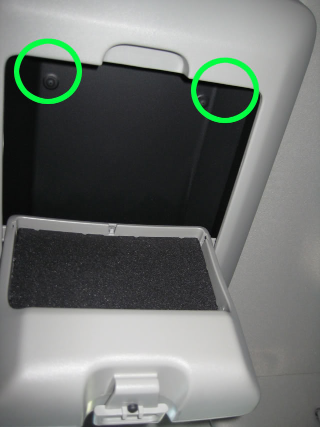
Map and Dome lights:
Step 1:
Take off the front cover by opening the overhead compartment and pulling down; however, do not pull too hard as there is a wire attached. Pull at points circled. And then detach wire.
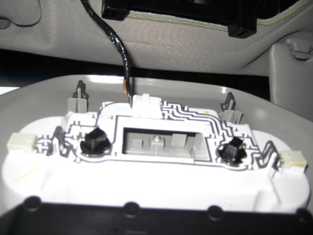
Step 2:
Take off back cover by pulling at the point circle.
Step 3:
Take out old light and insert new LEDs. (If they do not work flip them 180 degrees.)
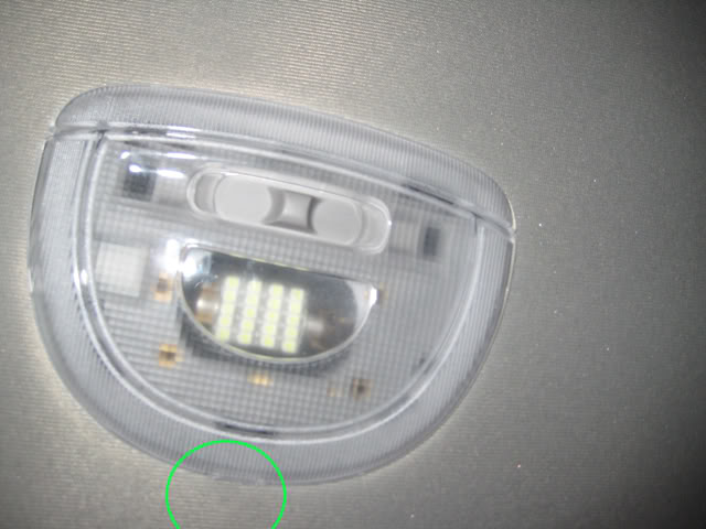
Step 4:
Put everything back together.
(Taken without flash.)
Door Switches beside driver’s side window switches:
(I would start with the switch used the least just in case you mess up and that way you can practice.)
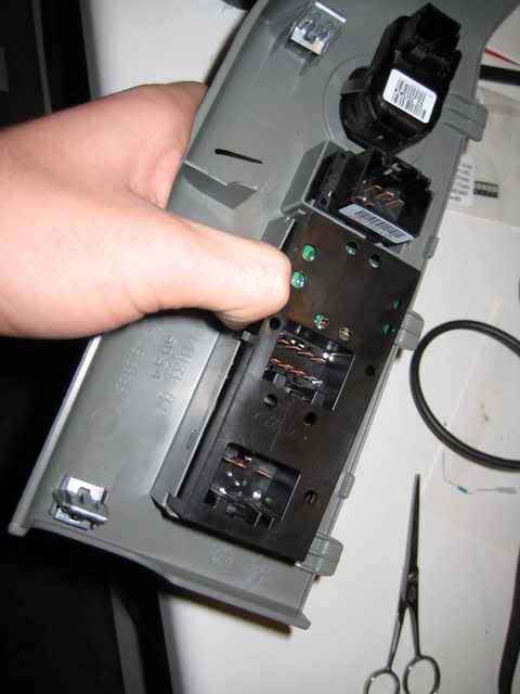
Step 1:
Take off the armrest cover by pulling up in the corner. (It should pop right off.)
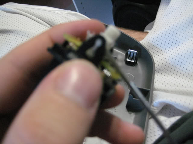
Step 2:
Disconnect the cables that are connected to the switches.
Step 3:
Take the switch out of the arm rest.
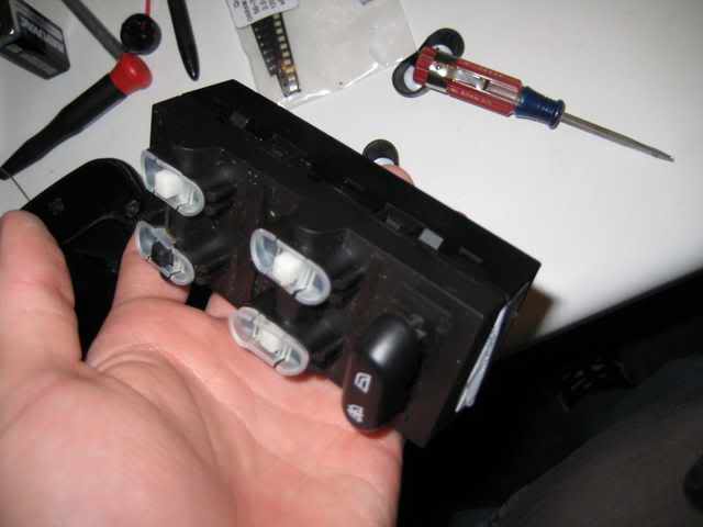
Step 4:
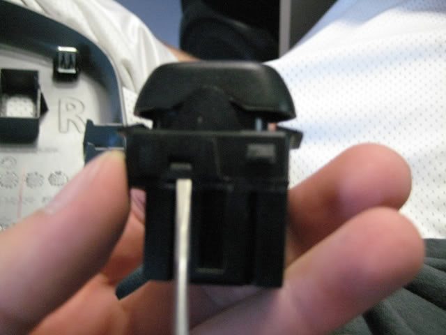
Take the part you would normally touch off the switch by just pulling.
Step 5:
Separate the top and bottom of the switch. Pull the white part afterwards.
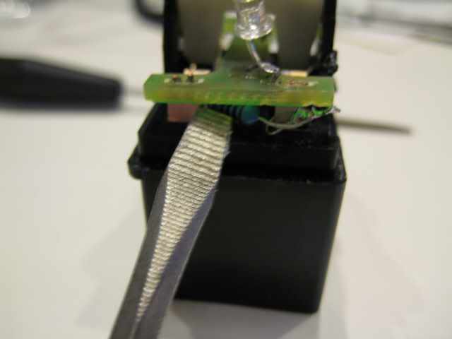
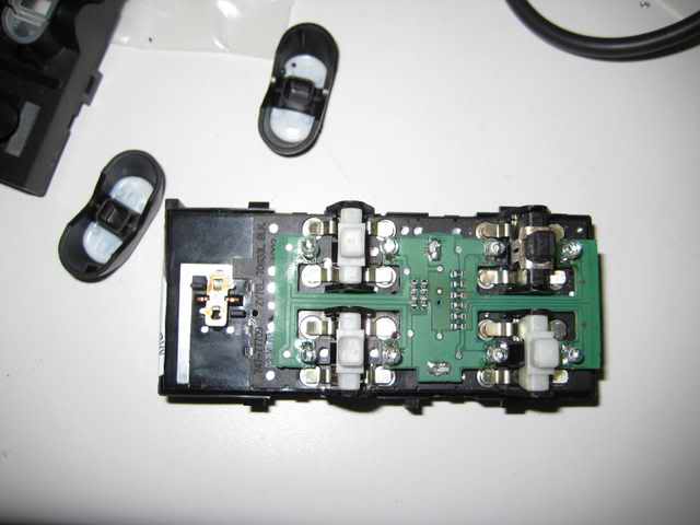
Step 6:
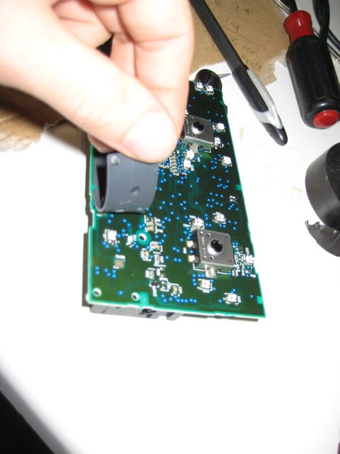
Pry the circuit board off with a flat head screwdriver.
Step 7:
De-solder all the things on the board. I don't have any pictures of this.
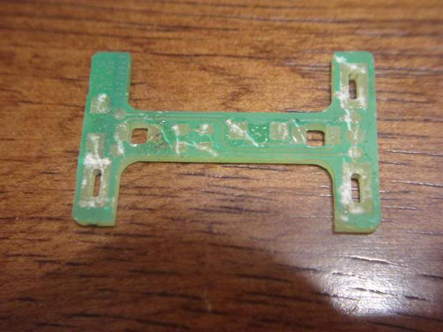
Step 8:
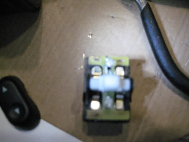
File the boards until there are no wires. Don’t worry about destroying the boards. (Should look like this when finished or be a yellowish color.)
Step 9:
Close the tabs with a pair of pliers. This is so you can put the circuit board back on later. I don't have any pictures of this.
Step 10:
Put the circuit board back onto the tabs. I don't have any pictures of this.
Step 11:
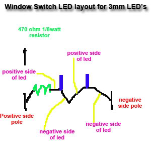
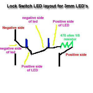
Wire up the LEDs using the following diagrams for window switches and unlock switches.
Step 12:
Make sure all LEDs are face up.
Step 13:
Go test the LEDs!!! Make sure they work.
Step 14:
Reassemble the switches.
Driver’s side window switch with 3mm LEDs (I recommend doing it this way so your LEDs match better):
Step 1:
Take off the armrest cover by pulling up in the corner. (It should pop right off, if not use a tiny screwdriver in the corner.)
Step 2:
Disconnect the cables that are connected to the switches.
Step 3:
Take the switch out of the arm rest.
Step 4:
Take the part you would normally touch off the switch by just pulling. Don't pull off the window lock switch.
Step 5:
Separate the top and bottom of the switch.
Step 6:
Cut the LED leads, remembering which side is positive, to about a quarter inch.
Step 7:
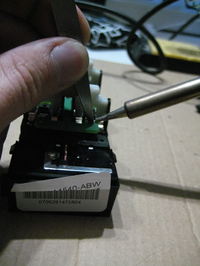
De-solder LEDs one at a time. (Circled)
Step 8:
Solder LEDs one at a time. Make sure you test for a good connection on each LED as they are wired in series.
Driver’s side window switch with 1206 LEDs:
Step 1:
Take off the armrest cover by pulling up in the corner. (It should pop right off, if not use a tiny screwdriver in the corner.)
Step 2:
Disconnect the cables that are connected to the switches.
Step 3:
Take the switch out of the arm rest.
Step 4:
Take the part you would normally touch off the switch by just pulling.
Step 5:
Separate the top and bottom of the switch.
Step 6:
De-solder each individual LED. (Circled)
*Test each LED after you solder it on for this step because all beside the driver’s window is wired in parallel, so when one is out both for that window go out. So if you do not test after each LED you will not be sure which LED is out if you do not solder correctly.*
Step 7:
*Test each LED after you solder it on for this step because all beside the driver’s window is wired in parallel, so when one is out both for that window go out. So if you do not test after each LED you will not be sure which LED is out if you do not solder correctly.*
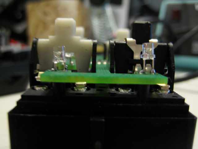
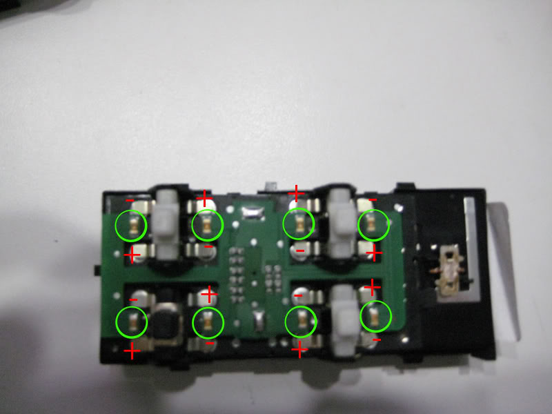
Solder the LEDs back on using the following technique. Use the last picture for positive and negative sides of LEDs. (As seen in the last picture the driver’s window switch isn’t the same as the others so keep this in mind.) (Next picture will show polarity of the LEDs.)
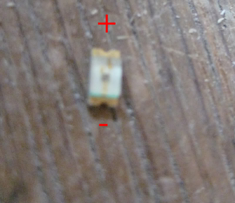
*On my LEDs there was a green line on the negative side. And also there were two wires on the positive side. This was on mine and I am not sure about all LEDs so make sure to test yours.*
Step 8:
Reassemble Switch.
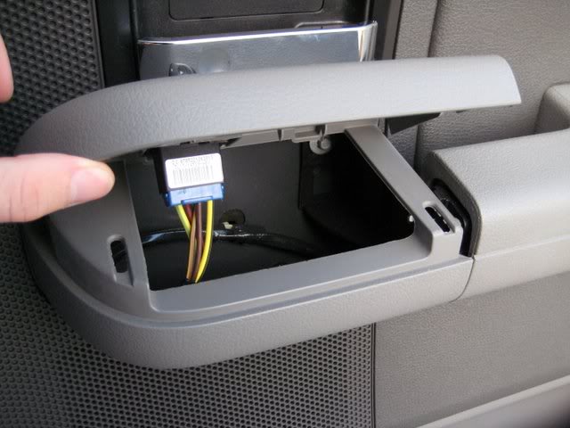
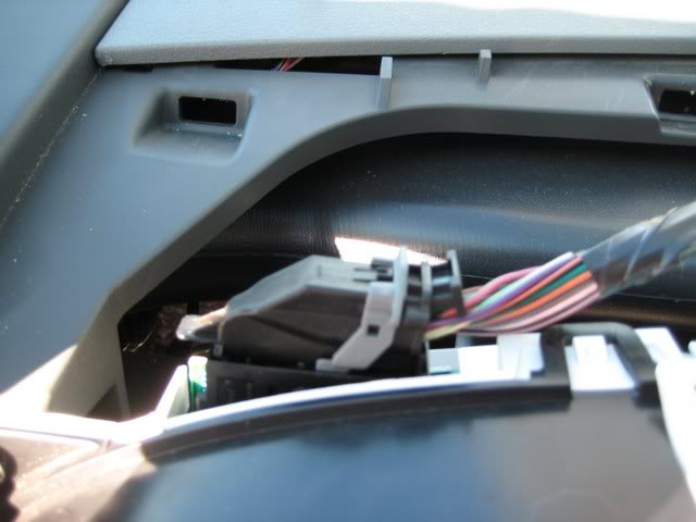
Reverse sensor switch:
Step 1:
Take off bezel around the radio being careful of the cords behind it. You will have to disconnect the cords in order to fully remove the bezel. Make sure you get the airbag one as this one is the most delicate.
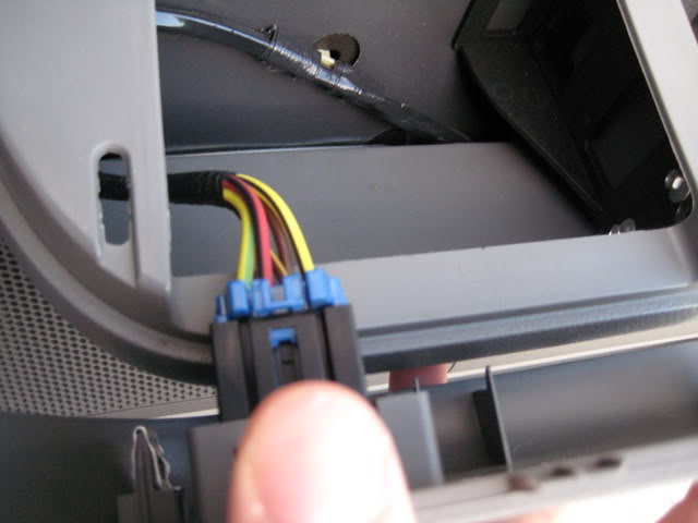
Airbag plug.
Step 2:
While compressing the tabs on the switch push out of the bezel.
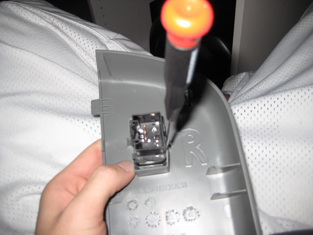
Step 3:
Pull top portion of the switch off. This will expose 2 LEDs.
Step 4:
Cut the green LED’s wires close to the LED itself. This will make soldering the new one a lot easier.
Step 5:
Solder using the following for polarity. I put in a resistor, I’m not sure if this is necessary but I figured since the one I was putting blow when I attached it to a 9V battery and the one out of the truck did not I took the safer choice.
Step 6:
Go test the LED. Press the switch a lot and make sure it doesn’t affect the movement of the switch; I had to file part of my switch to get it to work perfectly.
Step 7:
Put the switch back into the bezel.
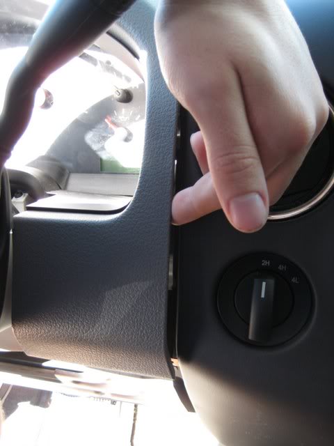
Headlamp switch:
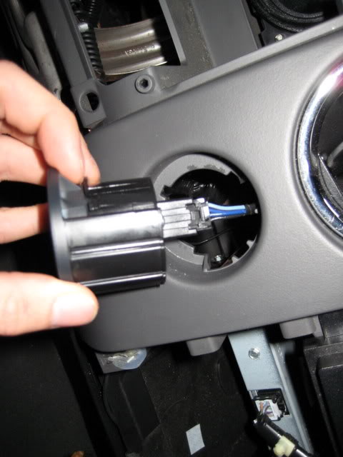
Step 1:
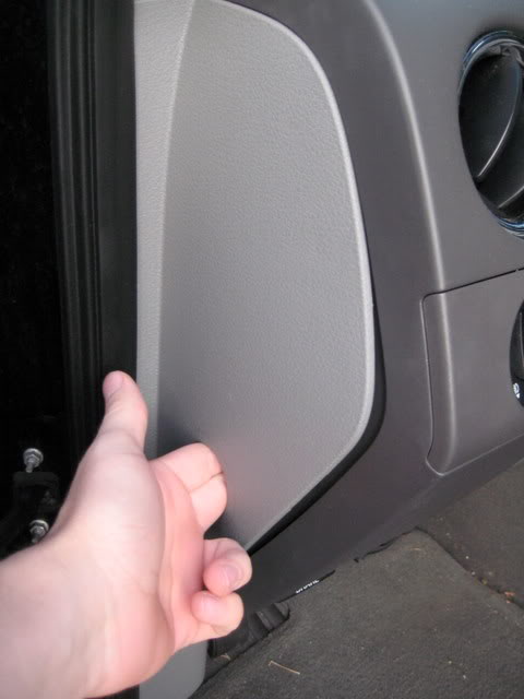
Remove the side panel by inserting a finger or into the hole on the side and pulling.
Step 2:
Find clip on the headlight switch. And squeeze, I used a pair of pliers because it was freezing outside and were very difficult to compress.
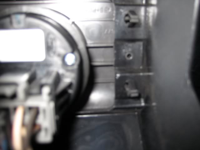
Step 3:
Disconnect the headlight switch and the dimmer.
Step 4:
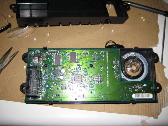
Remove the screws on the back of the headlight switch.
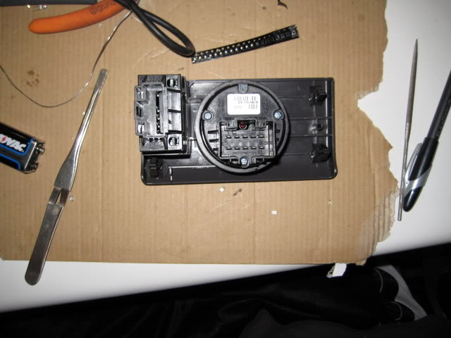
Step 5:
*I would go test after every LED, just in case.
De-solder and solder the circled LEDs. Follow picture for polarity. Or just have the "cut" part of the LED in the same place.
Step 6:
If you have not been testing all along, test.
Step 7:
Reassemble.
4WD Switch:
Step 1:
Take off bezel around the radio being careful of the cords behind it. You will have to disconnect the cords in order to fully remove the bezel. Make sure you get the airbag one as this one is the most delicate.
Step2:
Compress the tabs on the side of the switch, slide out.
Step 3:
Take the screw out of the back.
Step 4:
De-solder and solder the circled LEDs. Test after each.
Step 5:
Reassemble.
AC controls:
Step 1:
Take off bezel around the radio being careful of the cords behind it. You will have to disconnect the cords in order to fully remove the bezel. Make sure you get the airbag one as this one is the most delicate.
Step 2:
Use torx 20 screwdriver to separate the controls from the bezel.
Step 3:
Take the two pieces apart by compressing the tabs.
Step 4:
Use torx 10 screwdriver to unscrew the screws.
Step 5:
Pull the circuit board out of the front part of the AC controls.
Step6:
Take plastic piece at the bottom of the circuit board off.
Step 7:
De-solder LEDs one at a time and re-solder that one LED and go test after each LED. Repeat until finished. Use following diagrams for polarity and for which LEDs to redo. Use soldering technique from Driver’s side window switch portion of this tutorial. Also make sure to run a screwdriver through the center to make sure no solder is connecting the two poles.
Step 8:
Reassemble. Pat yourself on the back cause you have just finished the hard part unless you decide to do the more difficult cluster setup.
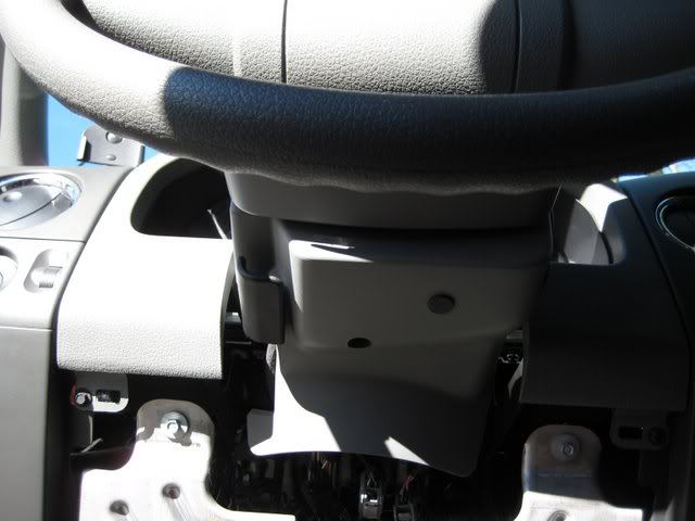
Instrument Cluster (easy way):
Step 1:
Remove the lower two screw on the bottom panel.
Step 2:
Remove the 2 screws on the upper panels that you just exposed. The little black ones.
Step 3:
Take your fingers and run them up the edge of the panel, to get the clips off.
Step 4:
Now you should be looking at the instrument cluster, remove the 4 screws.
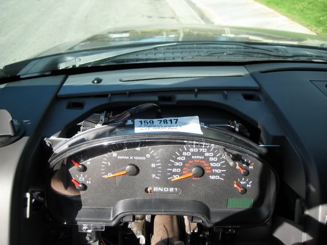
Step 5:
Remove the two plugs.
Step 6:
Remove the shifter by squeezing the two tabs.
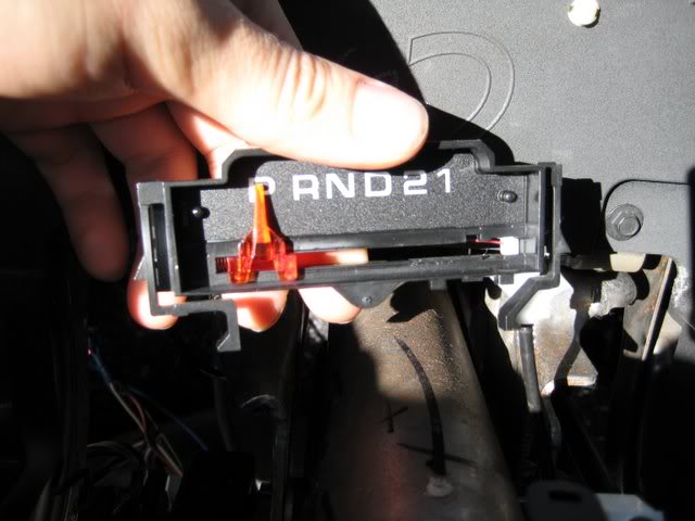
Step 7:
Take the shifter out by removing the red cord.
Step 8:
Remove the green from this with an X-Acto knife being careful not to remove anything besides the number or letter.
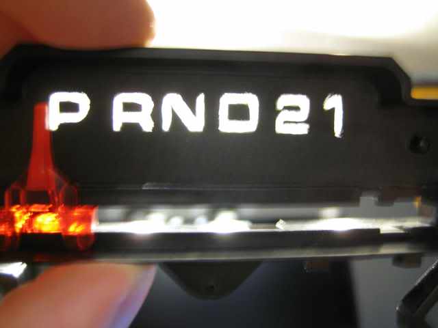
Step 9:
Take the clear plastic off the cluster.
Step 10:
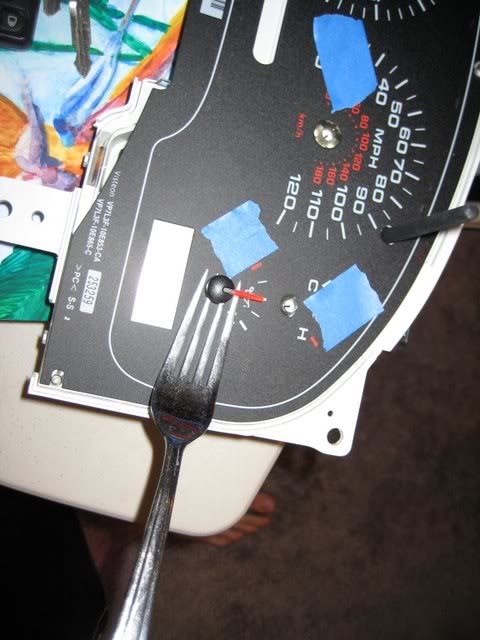
Remove the needles by using a fork and applying force, it takes quite a bit of force.
Step 11:
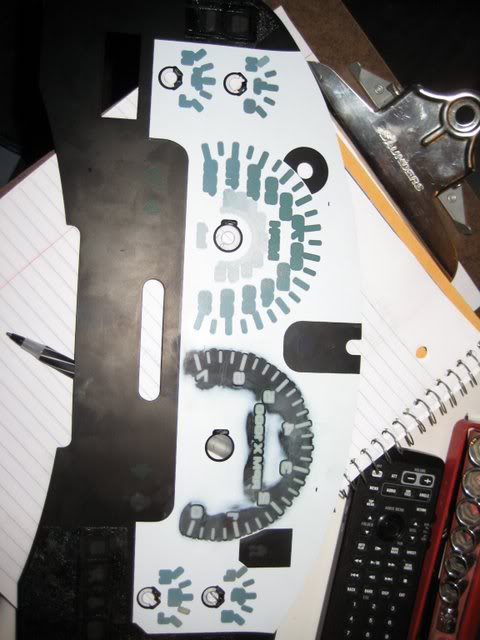
Peel off the gauge overlay.
Step 12:
Start sanding the green with 320 sandpaper. RPMs sanded the rest isn't.
Step 13:
You should be able to it up to the light and see no green through it.
Step 14:
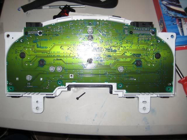
Now it is time to replace your lights, take a T15 Torx and unscrew the back screws on the cluster.
Step 15:
Take the clear diffuser off, the part you removed the black gauge from.
Step 16:
You should have exposed the circuit board now and you can you remove the LCD screen.
Step 17:
Take off LCD green backing.
Step 18:
Take out all of the old bulbs.
Step 19:
Put in LEDs and go test, flip the LEDs where necessary.
Step 20:
Reassemble
Steering Wheel Controls
Step 1:
Disconnect battery, just in case you have bad luck, you don't want the airbag blowing up in your face.
Step 2:
Wait 15 minutes.
Step 3:
Remove two 8mm bolts.
Step 4:
Remove airbag/horn.
Step 5:
Remove two bolts on each control.
Step 6:
Unplug harness.
Step 7:
Have better luck then me at getting them apart.
Step 8:
Take circuit boards out.
Step 9:
Desolder LEDs
Step 10:
Solder LEDs in same direction, "cut" in same the place, as the old ones.
Step 11:
Test.
Step 12:
Reassemble control, if you broke it you can use a drop of super glue.
Wow I just realized I don't have some pics I need. Other then the crappy output pictures of the original led cluster swap, only cause I only had this setup 45 minutes to decide I hated it because the needles didn't have any light through them, but if you have white or blue needles for a blue swap or red for a red swap you'll be ok.
Thanks to XPerties and Fabian06SC for your amazing work on being pioneers for the 3mm LED switch swap and the LED cluster swap.
I hope this helps a lot of people by combining everything into one tutorial.
This whole process took me about 10 hours, of course that was with doing all of the research I included here, re-doing the cluster now for the 4th time
, fighting with the driver's side window control because of no diagram and not realizing that the driver's window switch is different the then the rest in that control as outlined in the the diagrams included, and other things going wrong. If I did it again with the information, and with little experience, in this write-up I did I would say it should take no more then 4-5 hours.
I sadly don't have pictures for everything tonight but will have them tomorrow.
Well here's something I know everyone has been looking for. I will add all of the pictures by the end of the night, I just wanted to get it up. So please tell me if there are any errors or things that don't make sense. And of course feel free to ask any and all questions. I will eventually be adding a similar way of doing it like Fabian06SC's except with different LEDs because I feel that it is too bright doing it this way, as I have two the way he did it one with wide angle and one with narrow LEDs.
Supplies needed (With suggestion of where to buy everything, quantity, and what it’s for.):
1- 3mm LEDs (color of your choice) x 6-13 depending on amount of switches by cigarette lighter, amount of doors, and if you want to do the red blinking anti-theft light, buy 50 (for doors) Link
2- 1206 SMD LEDs (color of your choice) x 8* (for doors unless planning on using 3mm for exact match.) Link
3- PLCC-2 LEDs (color of your choice) x 20 for 4wd or 18 for 2wd, don't remember if I counted the steering wheel controls
* (for HVAC and headlight switch) Link4- 212 LED x1 (for dome light) Link
5- 194 LED x 2 (for map lights) Link
(This includes two. *The 194 bulbs will also work for license plate lights.*)
6- 470 ohm 1/4 watt resistor x 4 Link
Always buy extra in case one does not work or you mess up for the ones with an * next to their quantities.
Tools needed:
1- Lots of different size flathead screwdrivers
2- #1 or #2 Philips screwdrivers
3- T10, T15, and T20 Torx screwdrivers
4- Small needlenose pliers
5- Small wire cutters
6- Soldering iron and solder
7- File
8- 8mm socket and extension
9- 8mm wrench
10- X-Acto knives
11- Sandpaper
12- Resistor calculator (Check what resistors you need, for instance red LEDs require a 560 ohm 1/2 watt resistor so be sure to check, mine are for blue because most color LEDs use 3.0-3.2 v at 20 ma; whereas, red and some other colors use 1.8-2.0 v at 20 ma so if you don't get the right resistor your LEDs will fail faster.
Map and Dome lights:
Step 1:
Take off the front cover by opening the overhead compartment and pulling down; however, do not pull too hard as there is a wire attached. Pull at points circled. And then detach wire.
Step 2:
Take off back cover by pulling at the point circle.
Step 3:
Take out old light and insert new LEDs. (If they do not work flip them 180 degrees.)
Step 4:
Put everything back together.
(Taken without flash.)
Door Switches beside driver’s side window switches:
(I would start with the switch used the least just in case you mess up and that way you can practice.)
Step 1:
Take off the armrest cover by pulling up in the corner. (It should pop right off.)
Step 2:
Disconnect the cables that are connected to the switches.
Step 3:
Take the switch out of the arm rest.
Step 4:
Take the part you would normally touch off the switch by just pulling.
Step 5:
Separate the top and bottom of the switch. Pull the white part afterwards.
Step 6:
Pry the circuit board off with a flat head screwdriver.
Step 7:
De-solder all the things on the board. I don't have any pictures of this.
Step 8:
File the boards until there are no wires. Don’t worry about destroying the boards. (Should look like this when finished or be a yellowish color.)
Step 9:
Close the tabs with a pair of pliers. This is so you can put the circuit board back on later. I don't have any pictures of this.
Step 10:
Put the circuit board back onto the tabs. I don't have any pictures of this.
Step 11:
Wire up the LEDs using the following diagrams for window switches and unlock switches.
Step 12:
Make sure all LEDs are face up.
Step 13:
Go test the LEDs!!! Make sure they work.
Step 14:
Reassemble the switches.
Driver’s side window switch with 3mm LEDs (I recommend doing it this way so your LEDs match better):
Step 1:
Take off the armrest cover by pulling up in the corner. (It should pop right off, if not use a tiny screwdriver in the corner.)
Step 2:
Disconnect the cables that are connected to the switches.
Step 3:
Take the switch out of the arm rest.
Step 4:
Take the part you would normally touch off the switch by just pulling. Don't pull off the window lock switch.
Step 5:
Separate the top and bottom of the switch.
Step 6:
Cut the LED leads, remembering which side is positive, to about a quarter inch.
Step 7:
De-solder LEDs one at a time. (Circled)
Step 8:
Solder LEDs one at a time. Make sure you test for a good connection on each LED as they are wired in series.
Driver’s side window switch with 1206 LEDs:
Step 1:
Take off the armrest cover by pulling up in the corner. (It should pop right off, if not use a tiny screwdriver in the corner.)
Step 2:
Disconnect the cables that are connected to the switches.
Step 3:
Take the switch out of the arm rest.
Step 4:
Take the part you would normally touch off the switch by just pulling.
Step 5:
Separate the top and bottom of the switch.
Step 6:
De-solder each individual LED. (Circled)
*Test each LED after you solder it on for this step because all beside the driver’s window is wired in parallel, so when one is out both for that window go out. So if you do not test after each LED you will not be sure which LED is out if you do not solder correctly.*
Step 7:
*Test each LED after you solder it on for this step because all beside the driver’s window is wired in parallel, so when one is out both for that window go out. So if you do not test after each LED you will not be sure which LED is out if you do not solder correctly.*
Solder the LEDs back on using the following technique. Use the last picture for positive and negative sides of LEDs. (As seen in the last picture the driver’s window switch isn’t the same as the others so keep this in mind.) (Next picture will show polarity of the LEDs.)
*On my LEDs there was a green line on the negative side. And also there were two wires on the positive side. This was on mine and I am not sure about all LEDs so make sure to test yours.*
Step 8:
Reassemble Switch.
Reverse sensor switch:
Step 1:
Take off bezel around the radio being careful of the cords behind it. You will have to disconnect the cords in order to fully remove the bezel. Make sure you get the airbag one as this one is the most delicate.
Airbag plug.
Step 2:
While compressing the tabs on the switch push out of the bezel.
Step 3:
Pull top portion of the switch off. This will expose 2 LEDs.
Step 4:
Cut the green LED’s wires close to the LED itself. This will make soldering the new one a lot easier.
Step 5:
Solder using the following for polarity. I put in a resistor, I’m not sure if this is necessary but I figured since the one I was putting blow when I attached it to a 9V battery and the one out of the truck did not I took the safer choice.
Step 6:
Go test the LED. Press the switch a lot and make sure it doesn’t affect the movement of the switch; I had to file part of my switch to get it to work perfectly.
Step 7:
Put the switch back into the bezel.
Headlamp switch:
Step 1:
Remove the side panel by inserting a finger or into the hole on the side and pulling.
Step 2:
Find clip on the headlight switch. And squeeze, I used a pair of pliers because it was freezing outside and were very difficult to compress.
Step 3:
Disconnect the headlight switch and the dimmer.
Step 4:
Remove the screws on the back of the headlight switch.
Step 5:
*I would go test after every LED, just in case.
De-solder and solder the circled LEDs. Follow picture for polarity. Or just have the "cut" part of the LED in the same place.
Step 6:
If you have not been testing all along, test.
Step 7:
Reassemble.
4WD Switch:
Step 1:
Take off bezel around the radio being careful of the cords behind it. You will have to disconnect the cords in order to fully remove the bezel. Make sure you get the airbag one as this one is the most delicate.
Step2:
Compress the tabs on the side of the switch, slide out.
Step 3:
Take the screw out of the back.
Step 4:
De-solder and solder the circled LEDs. Test after each.
Step 5:
Reassemble.
AC controls:
Step 1:
Take off bezel around the radio being careful of the cords behind it. You will have to disconnect the cords in order to fully remove the bezel. Make sure you get the airbag one as this one is the most delicate.
Step 2:
Use torx 20 screwdriver to separate the controls from the bezel.
Step 3:
Take the two pieces apart by compressing the tabs.
Step 4:
Use torx 10 screwdriver to unscrew the screws.
Step 5:
Pull the circuit board out of the front part of the AC controls.
Step6:
Take plastic piece at the bottom of the circuit board off.
Step 7:
De-solder LEDs one at a time and re-solder that one LED and go test after each LED. Repeat until finished. Use following diagrams for polarity and for which LEDs to redo. Use soldering technique from Driver’s side window switch portion of this tutorial. Also make sure to run a screwdriver through the center to make sure no solder is connecting the two poles.
Step 8:
Reassemble. Pat yourself on the back cause you have just finished the hard part unless you decide to do the more difficult cluster setup.
Instrument Cluster (easy way):
Step 1:
Remove the lower two screw on the bottom panel.
Step 2:
Remove the 2 screws on the upper panels that you just exposed. The little black ones.
Step 3:
Take your fingers and run them up the edge of the panel, to get the clips off.
Step 4:
Now you should be looking at the instrument cluster, remove the 4 screws.
Step 5:
Remove the two plugs.
Step 6:
Remove the shifter by squeezing the two tabs.
Step 7:
Take the shifter out by removing the red cord.
Step 8:
Remove the green from this with an X-Acto knife being careful not to remove anything besides the number or letter.
Step 9:
Take the clear plastic off the cluster.
Step 10:
Remove the needles by using a fork and applying force, it takes quite a bit of force.
Step 11:
Peel off the gauge overlay.
Step 12:
Start sanding the green with 320 sandpaper. RPMs sanded the rest isn't.
Step 13:
You should be able to it up to the light and see no green through it.
Step 14:
Now it is time to replace your lights, take a T15 Torx and unscrew the back screws on the cluster.
Step 15:
Take the clear diffuser off, the part you removed the black gauge from.
Step 16:
You should have exposed the circuit board now and you can you remove the LCD screen.
Step 17:
Take off LCD green backing.
Step 18:
Take out all of the old bulbs.
Step 19:
Put in LEDs and go test, flip the LEDs where necessary.
Step 20:
Reassemble
Steering Wheel Controls
Step 1:
Disconnect battery, just in case you have bad luck, you don't want the airbag blowing up in your face.
Step 2:
Wait 15 minutes.
Step 3:
Remove two 8mm bolts.
Step 4:
Remove airbag/horn.
Step 5:
Remove two bolts on each control.
Step 6:
Unplug harness.
Step 7:
Have better luck then me at getting them apart.
Step 8:
Take circuit boards out.
Step 9:
Desolder LEDs
Step 10:
Solder LEDs in same direction, "cut" in same the place, as the old ones.
Step 11:
Test.
Step 12:
Reassemble control, if you broke it you can use a drop of super glue.
Wow I just realized I don't have some pics I need. Other then the crappy output pictures of the original led cluster swap, only cause I only had this setup 45 minutes to decide I hated it because the needles didn't have any light through them, but if you have white or blue needles for a blue swap or red for a red swap you'll be ok.
Last edited by lsracer; 02-05-2010 at 02:23 PM.
#2
02-04-2010, 11:20 PM


Join Date: Sep 2009
Location: Bluffton, SC
Posts: 2,178
Likes: 0
Received 0 Likes
on
0 Posts
#3
02-04-2010, 11:22 PM
#4
02-04-2010, 11:26 PM
Join Date: Sep 2009
Location: Bluffton, SC
Posts: 2,178
Likes: 0
Received 0 Likes
on
0 Posts

#5
02-04-2010, 11:29 PM
#6
02-04-2010, 11:33 PM
Join Date: Sep 2009
Location: Bluffton, SC
Posts: 2,178
Likes: 0
Received 0 Likes
on
0 Posts
#7
02-04-2010, 11:37 PM
I think I have too many pics. I think like 2000 for this project. So if I don't put one up that you need I probably have it or can get it.  But I'm doing the cluster right now the simple way and then back to the writing board to do the full LED circuit and steering wheel controls that I forgot about the first time I wrote it
I think like 2000 for this project. So if I don't put one up that you need I probably have it or can get it. But I'm doing the cluster right now the simple way and then back to the writing board to do the full LED circuit and steering wheel controls that I forgot about the first time I wrote it
Trending Topics
#8
02-04-2010, 11:51 PM
Join Date: Sep 2009
Location: Bluffton, SC
Posts: 2,178
Likes: 0
Received 0 Likes
on
0 Posts
 , so I decided to just do one.
#10
02-05-2010, 01:21 AM

#11
02-05-2010, 01:25 AM
#12
02-05-2010, 02:25 PM
#13
02-11-2010, 04:11 PM

Senior Member
Join Date: Jun 2006
Location: Maricopa, AZ
Posts: 4,719
Likes: 0
Received 0 Likes
on
0 Posts
#15
02-11-2010, 08:18 PM
Senior Member
Join Date: Jun 2006
Location: Maricopa, AZ
Posts: 4,719
Likes: 0
Received 0 Likes
on
0 Posts
still deciding, i still havnt pulled the cluster off and taken it apart, but from fabians thread im figuring on making a circuit board and use the plcc leds like on the a/c, i really like the way my ac came out. i did some research on how to make a circuit board at home, i have all the stuff to do it so i just need time now, gonna take the cluster apart, try to scan the overlay so i have some thing to lay it out with and draw it up in a cad program and print the circuit, transfer to some copper clad board, etch the copper, trim the circuit board and install. if it works well i will make several of these custom circuit boards and sell them