 |
How To Install A Remote Starter... |
Please let me start out by saying I cannot be held responsible for damages, errors, etc caused by or as a result of following these instructions. These instructions are provided as a guideline only - there is no substitute for checking each wire referenced in your vehicle with a digital multimeter to verify accuracy. As a reference, my vehicle is a 1998 Ford F150 Lariat Extended Cab with the 5.4 liter engine and factory alarm/keyless entry.
I bought a Crimestopper RS900ERIII Cool Start Remote Engine Starting System from eBay. More information can be found on this unit at http://www.crimestopper.com/rs900.html. After researching remote starters, I realized this unit had some features I was looking for including Factory Alarm Disarm, Remote Keyless Entry, and Idle-Down Mode.
Since I have the factory security system/keyless entry, I didn't want to carry two remotes around - one to control locking/unlocking/disarming and one for remote starting. I also liked the idle down mode allowing me to run into a convenience store, double-park, etc while keeping the truck running, locking the doors, and taking my keys with me.
Before I even looked under the dash or pulled out my digital multimeter, I looked around online for wiring diagrams. I found an awesome site with very accurate information at http://www.bulldogsecurity.com/wiringdiag.htm. This site not only has wire colors/locations for remote starters, but alarms as well.
Upon opening the box, a slight fear may occur when you see the bundle of wires included. Here is a picture of everything included in this kit:
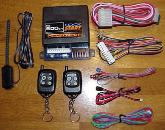
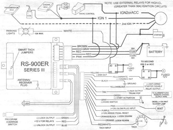
Fear not - every wire is not required! Out of the 21 possible wires, excluding the LED and switch, I only had to connect 13. Here's a scan of the wiring diagram included with this unit (click picture for a larger view in a new window):
Basically, here's a table of the wires I soldered into my truck:
| Crimestopper Wire | F150 Wire | F150 Wire Location | Wire Function |
|
12 PIN Plug: |
|||
| Black | N/A | Any Suitable Grounding Location | Ground |
| Gray | N/A | Hood PIN | Safety / Security |
| Purple | Light Green | Switch on brake pedal | Safety / Security |
| Orange / Black | Dark Green / Purple | Driver's Inside Upper-Left Firewall | Factory Alarm Disarm |
| Red / White | White / Pink | Powertrain Control Module Harness | Tachometer Sensor |
|
6 PIN Plug: |
|||
| Brown | Red / Light Blue | Ignition Harness | Below Steering Column |
| Gray | Gray / Yellow | Ignition Harness | Below Steering Column |
| Red | Yellow | Ignition Harness | Below Steering Column |
| Red | Yellow | Ignition Harness | Below Steering Column |
| Pink | Dark Blue / Green | Ignition Harness | Below Steering Column |
| White | Brown | Headlight Switch | Parking Lights |
|
3 PIN Door Lock Plug: |
|||
| Green | Pink / Yellow | Driver's Inside Upper-Left Firewall | Power Door Lock |
| Blue | Pink / Light Green | Driver's Inside Upper-Left Firewall | Power Door Unlock |
The first thing I did to make my life much easier was the removal of the driver's seat. This gave me plenty of extra room to work within the cab and only required the removing 4 T-55 TORX bolts and disconnecting 2 wires for the power seat. Obviously if you have a bench instead of captain's chairs your seat removal will be different. Here's a picture showing you how much room is gained without the seat in place:

Next, I needed to determine a location to install the "brain" of the unit. I choose to install the brain behind the heater floor plenum cover in the center of the dash at the hump in the middle of the floor. Removing the cover is as easy as removing a push pin from each side. If you look at the rear of the cover, you'll notice some plastic molding and foam - there's an area without foam or plastic that will allow the unit to fit perfectly. Here's a picture with the cover removed:

Next, I needed to determine a location to install the hood pin. Since the operation of the hood pin relies on a metal contact to ground the wire connected to it, I quickly realized that there wasn't too many choices since the area around the hood latch. To work around this, I drilled a hole and placed the supplied hood pin in the plastic near the hood latch and connected a wire from the pin to the bolt of the hood latch. I simply used a piece of scrap wire that was cut off of one of the other connections. I then ran the gray wire from the remote starter out to the hood pin, careful to route the wire along existing wire harness down the driver's side of the engine compartment and behind the grill and headlights. I entered the cab though the large rubber grommet near the top of the firewall. Here's a picture of the installed pin:

Next it was time to mount the programming button. This button is used to program the unit and to enable/disable valet mode. Since I'm not too eager to hack up my truck any more than need be, I wanted to find a pre-existing hole somewhere within reach from the driver's seat, but out of sight under the dash. Luckily, I found a hole in the metal bracket just above the parking brake. It was just a little too small, so I simply enlarged it a bit with a drill and the button slipped right in, with the back of the switch just clearing the parking brake. Here's a picture of its location:

Now comes the part I'm really proud of - the mounting of the LED. Again, not wanting to hack up my truck too much, I needed to find a location to mount the LED to be clearly visible from inside and outside the truck. I chose the plastic bolt cover on the top of the dash near the defroster ducts. These plastic covers simply pop off to reveal the bolt securing the dash. I removed the cover, drilled a small hole in the middle, popped the LED into the hole, slipped the wires down the dash and reinstalled the cover. This provided a clean, professional-looking install - almost like it came from the factory! Take a look:

Now comes the time to put your soldering skills to the test. I couldn't get a good picture of the ignition harness, but you can't miss it - it's the harness running down the steering column with quite a few larger gauge wires. I simply removed about 1/4" of the insulation, wrapped the new wire around the exposed wire, soldered, and taped for each connection. Five of the six wires in the 6 wire pin are connected to wires in this harness. The door lock/unlock wires and the factory disarm wire are connected to the harness plugged into the box in the upper corner of the driver's side firewall. Again, I couldn't get a good picture this far up under the dash, but you'll see it fairly quickly, especially when you know what color wires you're looking for. I unplugged this harness, soldered the three wires, and reconnected the harness.
One final wire connection, and the most time consuming, is the tachometer wire connection. This wire is found in the harness exiting the Powertrain Control Module (PCM). Unfortunately, this harness has about 75 wires tightly packing into one small area. I found it easy to remove the battery, tray, and PCM to provide easy access to this harness. The harness/PCM is removed by loosening the 10 mm bolt in the middle of the harness. Once you start digging though the wires in this harness, you'll eventually find the white/pink wire - solder the tachometer wire from the remote starter to this and reinstall the battery tray and battery. I slipped the tachometer wire out though the hole in the firewall where the computer and harness connect. Since there is a rubber grommet around the computer, there is no real fear of the wire chaffing or being pinched/cut/grounded. Thanks to Chris Duke for allowing me to use his picture of the PCM wiring harness from his Superchip installation. I couldn't get a decent picture from my truck - I seemed to have more components blocking the view to my harness:

The last thing I did was the mounting of the antenna. I ran the wire across the dash (underneath of course) and up the driver's side A pillar. This provides great distance to operate the remote for both remote starting and locking/unlocking the doors. Here's a picture with the antenna mounted and the trim still removed:

Overall, I'm pleased with the installation and features of this unit. The instructions did not provide much detail, but I've definitely seen worse. My only two dislikes so far are:
The interior lights no longer illuminate after unlocking via the key fob. When I have some time and it's not so cold, I plan to look into which wire I could connect the unlock wire to to simulate the key press of the factory unlock.
The anti-grind feature is optional, requiring the purchase and installation of a relay. I plan to buy a 12V 30A relay and install soon. This will prevent the starter motor from engaging when inserting the key and turning too far while the engine is already running from the remote starter.
When you compare the total cost of $59 including shipping vs. the advertised prices of around $175 for an installed unit a the local electronics stores, I'm glad I decided to do this myself. Please make sure you set aside plenty of time for the installation - the tight spaces and multiple wire hookups take some time. I highly recommend taking out the driver's seat for the installation - these four bolts and two wire harnesses are definitely worth the time. If you have a bench seat, I'm sure the removal is just as easy and without the wire harnesses.
If you have any questions, I'll certainly try to help! You can reach me at my email address in the header of this article. Good luck!