
Dynatech Headers & Bassani Cat back How To
#16
 07-11-2005, 04:34 AM


Join Date: May 2003
Location: Corpus Christi, TX
Posts: 598
Likes: 0
Received 0 Likes
on
0 Posts
20.I didn’t pre-install any of the header bolts on the bottom because I was concerned that the header might get hung up on them as I tried to install it from the bottom. You may want to install the header bolts on the bottom about halfway screwed in but the header may hang up on one or more of the bolts. The bolts are very easy to install once the header is in place so I recommend that you just wait until you stab the header before installing any bolts. If you do decide to install the bottom header bolts head the sign below.

21.From the bottom of the truck slide the header up through the opening as shown in Photo #33 below. When you get the exhaust manifold section of the header up in there a ways you need to start manipulating the header by twisting and turning it as you continue pushing it up and forward and it will go right into position. I did this by myself with no help and you can do it too. Once you get it into position it will hang by itself as shown in Photo #34 and you can now move to the fender well area.


21.From the bottom of the truck slide the header up through the opening as shown in Photo #33 below. When you get the exhaust manifold section of the header up in there a ways you need to start manipulating the header by twisting and turning it as you continue pushing it up and forward and it will go right into position. I did this by myself with no help and you can do it too. Once you get it into position it will hang by itself as shown in Photo #34 and you can now move to the fender well area.
#17
07-11-2005, 04:35 AM
Join Date: May 2003
Location: Corpus Christi, TX
Posts: 598
Likes: 0
Received 0 Likes
on
0 Posts
22.If you didn’t install all of the bottom header bolts prior to installing the header then move the header out of your way and install them now. Screw them about halfway in. Slide the header onto the bottom bolts and insert the Dynatech supplied SS gasket between the header and the head. You will have to support the header as you insert the gasket because the header wants to **** down which will close the gap at the bottom and prevent the gasket from setting in properly. Dynatech recommends that these gaskets be used dry so do not use any sealant. Don’t worry they will provide a perfect seal once buttoned up. After the gasket is installed, install the top header bolts and snug down all header bolts. The bolts that are toughest to get to are the 2 bottom rear bolts and the top rear bolt but if you have a Ľ” drive ratchet, 6” long extension and 10 mm swivel socket they are simple to get to as shown in Photos #35, #36 and #37.


#19
07-11-2005, 04:37 AM
Join Date: May 2003
Location: Corpus Christi, TX
Posts: 598
Likes: 0
Received 0 Likes
on
0 Posts
23.After all bolts are snug, begin tightening bolts using pattern shown below in Photo #38. There is no way to get a torque wrench on the header bolts so after making one pass using the pattern below, repeat process. Continue this process until all header bolts are tight. This is exactly how I did it and no header leaks as of yet. It will take several passes to properly tighten the bolts so be patient. One thing to keep in mind is that your are tightening bolts into an aluminum head so take care not to over torque the bolts.

This photo is courtesy of Martin (AKA I’D WIN) on NLOC

This photo is courtesy of Martin (AKA I’D WIN) on NLOC
#20
07-11-2005, 04:39 AM
Join Date: May 2003
Location: Corpus Christi, TX
Posts: 598
Likes: 0
Received 0 Likes
on
0 Posts


#21
07-11-2005, 04:40 AM
Join Date: May 2003
Location: Corpus Christi, TX
Posts: 598
Likes: 0
Received 0 Likes
on
0 Posts
25.Install bolt that secures ground wire and wire loom retainer to frame. This is the bolt removed in step #12. Make sure the wire loom is not lying up against header. Reconnect electrical connectors (passenger side only) that go to front brake. These are the connectors that were disconnected in step #12.
26.Progress check = Passenger side header should be installed and header bolts properly tightened. The transmission dipstick tube should be installed to where it is not resting against the header. The ground wire and wire loom retainer should be bolted to the frame. The wire going to the front passenger side brake should be reconnected. If this is all complete then move to the driver side to install the header.
27.Now begin the header install for the driver side. Coat the header bolts with a nice coat of high temp anti-seize. Install all the bottom header bolts on the driver side. Screw the bolts in about half way as shown in Photo #43.
#22
07-11-2005, 04:41 AM
Join Date: May 2003
Location: Corpus Christi, TX
Posts: 598
Likes: 0
Received 0 Likes
on
0 Posts
28.Install driver side header from the bottom. Once the header is sitting stable move back to the wheel well. Place the header over the bottom bolts and slide in the Dynatech SS gasket as shown in Photo #44. Again support the header as the gasket is installed to prevent the header from ****ing downward and closing the gap which will prevent the gasket from sliding into place. Once the gasket is in place, install the top header bolts. As mentioned before keep the weight of the header off of the bolts until you have 3-4 good full turns on the bolt. Once the remaining bolts are installed, snug down all of the header bolts. Again the bolts are 10 mm. You can access all of the top bolts from the top and all of the bottom bolts from the bottom as shown in Photo #45. You will need several extensions to reach the bottom bolts from the bottom. When all bolts are snug move to step #29.


#23
07-11-2005, 04:42 AM
Join Date: May 2003
Location: Corpus Christi, TX
Posts: 598
Likes: 0
Received 0 Likes
on
0 Posts
29.Now that all header bolts are snug, begin tightening bolts using pattern shown below in Photo #46. There is no way to get a torque wrench on the header bolts so after making one pass using the pattern below, repeat process. Continue this process until all header bolts are tight. This is exactly how I did it and no header leaks as of yet. It will take several passes to properly tighten the bolts so be patient. One thing to keep in mind is that your are tightening bolts into an aluminum head so take care not to over torque the bolts.
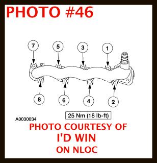
This photo is courtesy of Martin (AKA I’D WIN) on NLOC
This photo is courtesy of Martin (AKA I’D WIN) on NLOC
#24
07-11-2005, 04:44 AM
Join Date: May 2003
Location: Corpus Christi, TX
Posts: 598
Likes: 0
Received 0 Likes
on
0 Posts
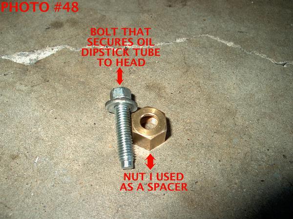
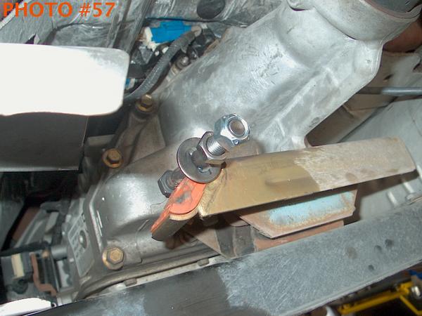
30.Apply a good coat of anti-seize to the EGR bung threads on the driver side header. Attach the EGR to the EGR bung and tighten using a 1Ľ” wrench. Re-install the oil dipstick tube. Make sure it seats good. You will face a similar problem as with the transmission dipstick tube. The oil dipstick tube will rest against the header unless you shim between the tube bracket and mounting tab on the head. You can use a good size nut as a spacer or stack washers between the bracket and the mounting tab to get the tube off of the header. I used a nut between the bracket and mounting tab as a spacer plus I bent the tube. You can choose whatever method suits you best just make sure you get the tube off of the header. I will explain what I did to rectify this issue in case you want to do the same thing.
I started the bolt through the tube bracket into the mounting tab on the head just as if it were going to be regularly installed. I got about 3 or 4 good full turns on the bolt then wedged a Ľ” extension between the tube and the header. I slowly tightened the bolt so as to not break the tube. I tightened the bolt almost all the way. Then I removed the bolt, placed a brass nut on the backside of the tube bracket, stuck the bolt through the bracket and nut and screwed it into the mounting tube. The following photos may illustrate what I did better than I can explain it.


I started the bolt through the tube bracket into the mounting tab on the head just as if it were going to be regularly installed. I got about 3 or 4 good full turns on the bolt then wedged a Ľ” extension between the tube and the header. I slowly tightened the bolt so as to not break the tube. I tightened the bolt almost all the way. Then I removed the bolt, placed a brass nut on the backside of the tube bracket, stuck the bolt through the bracket and nut and screwed it into the mounting tube. The following photos may illustrate what I did better than I can explain it.

#26
07-11-2005, 04:46 AM
Join Date: May 2003
Location: Corpus Christi, TX
Posts: 598
Likes: 0
Received 0 Likes
on
0 Posts
31.Reconnect electrical connectors that go to front brake. These are the connectors that were disconnected in step #12.
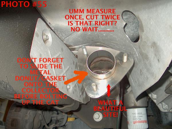
32.Now carefully apply high temp anti-seize on O2 sensor threads and header collector bolt threads. Install front O2 sensors into the high flow cats. Remember passenger side sensor in passenger side cat and driver side sensor in driver side cat. Take each cat and mock mount it to measure where the hole in the heat shield needs to be to accommodate the O2 sensor. Use a drill and a 1˝” – 1 7/8” hole saw rated for metal to cut the holes for the O2 sensors. Slide the metal donut on the collector and Install the cats using the 15 mm nuts supplied by Dynatech. You will need a 15 mm offset box wrench to tighten the collector nuts as they are a bit recessed. Use care when feeding the O2 sensor through the hole cut in the heat shield. Once the cats are secure, tighten the flange evenly. Connect the O2 sensor male connectors to the extension female connectors. Follow the extensions back to where they connect with the connectors between the firewall and the motor. Make sure they are not touching the headers anywhere. If it even looks close secure them away from the headers with plastic tie straps. Below are some photos that may add value here.


32.Now carefully apply high temp anti-seize on O2 sensor threads and header collector bolt threads. Install front O2 sensors into the high flow cats. Remember passenger side sensor in passenger side cat and driver side sensor in driver side cat. Take each cat and mock mount it to measure where the hole in the heat shield needs to be to accommodate the O2 sensor. Use a drill and a 1˝” – 1 7/8” hole saw rated for metal to cut the holes for the O2 sensors. Slide the metal donut on the collector and Install the cats using the 15 mm nuts supplied by Dynatech. You will need a 15 mm offset box wrench to tighten the collector nuts as they are a bit recessed. Use care when feeding the O2 sensor through the hole cut in the heat shield. Once the cats are secure, tighten the flange evenly. Connect the O2 sensor male connectors to the extension female connectors. Follow the extensions back to where they connect with the connectors between the firewall and the motor. Make sure they are not touching the headers anywhere. If it even looks close secure them away from the headers with plastic tie straps. Below are some photos that may add value here.

#28
07-11-2005, 04:48 AM
Join Date: May 2003
Location: Corpus Christi, TX
Posts: 598
Likes: 0
Received 0 Likes
on
0 Posts
33.It’s time to install the mid pipes. First install the support bolt for the driver side mid pipe in the clamp located on the transmission cross member support. This is the clamp that supported the hanger for the OEM exhaust. It’s the clamp that the bolt was removed from in step #7. Apply anti-seize to the rear O2 sensor threads and Dynatech band clamp bolts. Remember passenger side sensor in passenger side mid-pipe and driver side sensor in driver side mid pipe. Take one of the band clamps provided by Dynatech, snug it up using a 9/16” deep socket and slide it on the driver side cat. Now slide the driver side mid pipe into the band clamp. The driver side mid pipe has a bracket that attaches to the support bolt in the clamp on the transmission cross member. Make sure to slide the bracket over the support bolt when sliding the mid pipe into the band clamp on the cat. Snug the clamp down a little more, just enough to where the mid pipe will still rotate inside the band clamp. See photos below for illustration of some of the items discussed above.
After the driver side mid pipe is installed, repeat the process for the passenger side mid pipe. Once the mid pipes are snug in the band clamps, connect the O2 sensor male connectors to the female connectors above the tail of the transmission. Thoroughly inspect from header collector flanges up to motor for electrical wiring that may be too close to the header and reroute or secure any wires found touching or too close to headers


After the driver side mid pipe is installed, repeat the process for the passenger side mid pipe. Once the mid pipes are snug in the band clamps, connect the O2 sensor male connectors to the female connectors above the tail of the transmission. Thoroughly inspect from header collector flanges up to motor for electrical wiring that may be too close to the header and reroute or secure any wires found touching or too close to headers


#30
07-11-2005, 04:53 AM
Join Date: May 2003
Location: Corpus Christi, TX
Posts: 598
Likes: 0
Received 0 Likes
on
0 Posts


RECAP OF PROGRESS TO THIS POINT
·Headers installed bolts tight
·Header bolts coated with high temp anti-seize
·Front and rear O2 sensor threads coated with high temp anti-seize
·Header collector bolt threads coated with high temp anti-seize
·Dynatech tube clamp bolt threads coated with high temp anti-seize
·EGR bung threads on driver side header coated with high temp anti-seize
·EGR tube reconnected to EGR bung on driver side header and tight
·Transmission dipstick tube is installed and secured so it is not resting on header
·Oil dipstick tube is installed and secured so it is not resting on header
·Electrical wires running to front brakes reconnected
·Bolt that secures ground wire and wire loom retainer to frame on passenger side installed and tight
·Holes drilled in heat shield on driver and passenger side to accommodate front O2 sensors
·Front O2 sensors installed in O2 bungs on high flow cats
·High flow cats installed with metal collector donut/gasket in place and tightened evenly
·Front O2 sensor wires connected, routed away from header and secured if needed
·Rear O2 sensors installed in O2 bungs on mid pipes
·Mid pipes installed and band clamps are just snug enough to allow for rotation of mid pipes
·Rear 02 sensor wires reconnected
·Passenger side rear O2 connector re-attached to bracket
·Single electrical connector next to passenger side rear O2 connector on top tail of transmission is reconnected

