PIAA 520 Driving Light Wiring Options
#16
 01-11-2008, 01:52 PM


Senior Member
Join Date: Jul 2005
Location: Illinois.
Posts: 288
Likes: 0
Received 0 Likes
on
0 Posts
#17
01-11-2008, 02:33 PM


What trim level is your truck ?
Just want to give you a few idea, but need to know what options you have to do this. Your profile is blank.
The cigar lighter / front power point are constant power, so you would be able to accidentally leave them on if you use this as the power for the switch to the relay.
Just want to give you a few idea, but need to know what options you have to do this. Your profile is blank.
The cigar lighter / front power point are constant power, so you would be able to accidentally leave them on if you use this as the power for the switch to the relay.
#18
01-11-2008, 02:39 PM
Senior Member
Join Date: Jul 2005
Location: Illinois.
Posts: 288
Likes: 0
Received 0 Likes
on
0 Posts
#19
01-11-2008, 03:04 PM
Senior Member
Join Date: Jul 2005
Location: Illinois.
Posts: 288
Likes: 0
Received 0 Likes
on
0 Posts
#20
01-11-2008, 03:08 PM

#21
01-11-2008, 03:12 PM
Originally Posted by jbholmes
..<snip>... appears to be used for optional traction control system which I don't have. It has a switched power supply - see any concerns with using this as my proper point for the rocker switch?
This is Circuit 640, red w/ Yellow stripe wire.
The items on this are :
1. Instrument Cluster
1.1. This is the input to the cluster VPWR
2. Floor Shifter ( don't think this is for you with an XLT ?? )
3. Overdrive cancel switch
3.1. This is the input ( via the switch ) to the PCM on C1758 pin 45.
4. Traction Control ( not a concern to you, you don't have this ).
If you install an inline fuse to your tap close to the unused connector for the traction control, with a 1A fuse you should be OK. Any problems with the circuit should take out the smaller fuse first ( 1A ), and the load from the coil on the relay is very small ( 0.02 A )
Another option is to see if you have power in either side of Fuse position F18.
This is the fuse for the heated seats, hot in start / run position.
If one side of the the socket is hot in the run position, you can use an add-a-fuse in this slot to get power for your switch. Just leave the fuse slot on the add-a-fuse empty for the heated seats ( if you do not have them, else put the 10A in the add-a-fuse ).
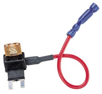
Let us know what you think of these 2 options. I would lean towards the fuse slot for the heated seats control, vs using something that is already in use on your truck.
PS : fordsoldier - Thanks for the info on his truck.
#22
01-11-2008, 03:17 PM
Senior Member
Join Date: Jul 2005
Location: Illinois.
Posts: 288
Likes: 0
Received 0 Likes
on
0 Posts
thats the way I had mine done.
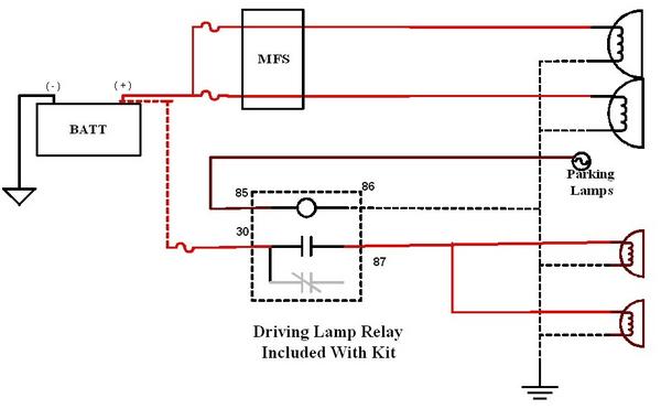
follow this diagram
http://www.kchilites.com/faq/instruc...layDiagram.pdf
The supply for the switch I taped the brown wire so I could use my lights when my other lights were on. It also gives you the chime, which I liked.
I had the relay under my hood on the drivers side by the air intake hole on the fender.
85 pin grounded on the fender wall
87 Pin run to the positive side of your lights
30 pin ran to battery.
86 pin run through fire wall to your switch.
ground on your switch run to ground on cigarett lighter
your load for the switch will be the wire you run though the fire wall
and your supply run to the brown wire on your head lame switch.
I put an inline fuse from the battery going to pin 30
I also put a inline fuse on the line going to the brown wire to the head light switch
that was just me taking a extra safty precaution.
#23
01-11-2008, 03:21 PM
F18 appears to control the PAM, compass, heated seats, electrochromatic mirrors, passenger airbag module, security system etc.. I have all of that except the heated seats. Looking at the fuse block, F20 - auxilary power point is located overhead for the dvd/monitor system which i don't have. Can I use this spot since nothing else is on that fuse position?
FordSoldier - what size fuse from battery to relay?? Also, you grounded the realy to the fender, where did you ground the lights themselves?
FordSoldier - what size fuse from battery to relay?? Also, you grounded the realy to the fender, where did you ground the lights themselves?
Last edited by jbholmes; 01-11-2008 at 03:37 PM.
#24
01-11-2008, 05:36 PM
Senior Member
Join Date: Jul 2005
Location: Illinois.
Posts: 288
Likes: 0
Received 0 Likes
on
0 Posts
#25
01-11-2008, 05:43 PM
#26
01-11-2008, 05:46 PM
Senior Member
Join Date: Jul 2005
Location: Illinois.
Posts: 288
Likes: 0
Received 0 Likes
on
0 Posts
#27
01-11-2008, 05:52 PM
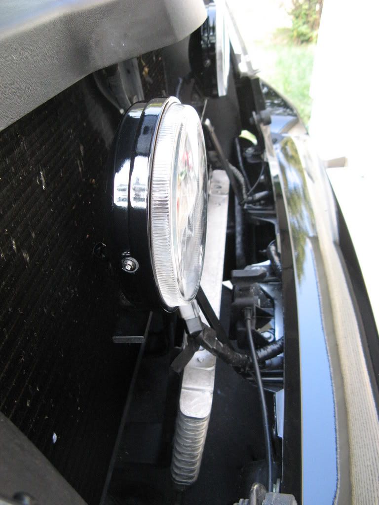
Will do, already started :-) One last question - the connectors on the lights seem like they would be prone to moisture esp when mounted on a bull bar... Did you ever have any probs??
Also - happen to have a pick of where you grounded to on the right side??
Also - happen to have a pick of where you grounded to on the right side??
Last edited by jbholmes; 01-11-2008 at 06:02 PM.
#28
01-11-2008, 05:54 PM
Senior Member
Join Date: Jul 2005
Location: Illinois.
Posts: 288
Likes: 0
Received 0 Likes
on
0 Posts
#29
01-11-2008, 05:56 PM
Originally Posted by jbholmes
F18 appears to control the PAM, compass, heated seats, electrochromatic mirrors, passenger airbag module, security system etc.. I have all of that except the heated seats...<snip>...
All set, hot in run position, so it will not flash your AUX lights when you lock the truck.
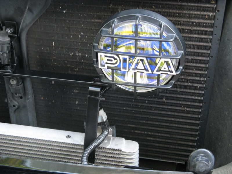
Just an FYI, my 520s & 510s in my PIAA airdam, I used the stock connectors, and did not have any problems with them for the 5 years installed.
A guy I ride motorcycles with has the 520s on a light bar on his ZG, and have not had a problem with the connectors either. They are better then you think.
I did not wrap them with tape, as if they get wet, you want them to be able to dry out. buried in electrical tape will hamper this.
This is very similar to what you are going to be installing, but instead of the brown from the parking lamps, you are going to be usign the lead from the add-a-fuse in F18.
The fuse size should be in the kit from PIAA, I think they use a 20 A ??? ( don't have 520s around any more.
Last edited by SSCULLY; 01-11-2008 at 05:59 PM.