Anyone have fuse box wiring diagrams for lights?
#1
 05-05-2004, 09:45 PM


Join Date: Jan 2004
Location: Chicago, Illinois
Posts: 272
Likes: 0
Received 0 Likes
on
0 Posts
Anyone have fuse box wiring diagrams for lights?
I'm working on the fog light mod. If you're not familiar with it, it allows you to turn the fog lights on with the switch in the parking light position also.
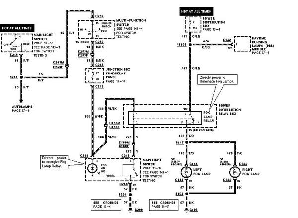
However, apparently, the hot lead coming into the switch that provides power for the foglamp relay (a white/black lead that runs to terminal #2 on the switch) isn't hot unless the headlamps are on. So, in order to use the fog lights in the parking position, the instructions make you bridge the switched (outgoing) lead from the switch that heads to the parking lamp relay (from terminal #12 on the switch runs a brown lead to the parking lamp relay) to the fog lamp relay (semi) hot power lead. (Basically, it puts the load for the fog lamp relay onto the parking lamp relay fuse (fuse #6 in the power distribution box) instead of on the fog lamp relay fuse (#27 in the fuse box)).
Most people haven't reported any problems, but several say that the connection tends to blow the #27 fuse (the fog lamp relay fuse). I'm hesitant to bridge the leads. Besides diverting the load for the fog relay, I'm assuming the bridge also powers the parking light relay from the fog lamp relay when the headlights are on, which can't be good.
So, I'm wondering first, if this is really what's happening, and second, if I can just make the fog lamp relay lead hot all the time. If anyone can post or send the diagrams for the headlight relay and multifunction switch (fuse #3 in the power dist box), the parking lamp relay and main light switch (fuse #6 in the power dist box) and the fog lamp relay and main light switch (fuse #27 in the small fuse box), I'd like to read through them and post a better fix for the mod.
Thanks for any help!
Last edited by ILLINI-SVT; 05-05-2004 at 09:47 PM.
#2
05-06-2004, 12:54 AM

Member
Join Date: Mar 2004
Location: La Vernia, TX
Posts: 28
Likes: 0
Received 0 Likes
on
0 Posts
I don't know how much the wiring has changed, but I found these diagrams for the foglamps and headlamps of a 1998 expedition. Hope they help.
FOGLAMPS
https://www.f150online.com/galleries...6093-91622.jpg
HEADLAMPS
https://www.f150online.com/galleries...6093-91623.jpg
FOGLAMPS
https://www.f150online.com/galleries...6093-91622.jpg
HEADLAMPS
https://www.f150online.com/galleries...6093-91623.jpg
#3
05-06-2004, 11:57 AM
Join Date: Jan 2004
Location: Chicago, Illinois
Posts: 272
Likes: 0
Received 0 Likes
on
0 Posts
Seriously, thanks, I think that's exactly what I was looking for. Not to be a pain, but if you by chance have the diagram for what appears to be the "Main Light Switch" "on page 13-17", my quest would be complete! 
It looks from the foglight diagram you posted that the power for the fog relay indeed comes only when the headlights are in the on position. If I can determine what lead heading into the switch itself is hot, I can just bridge that one to the fog lamp power lead to make it hot all the time (at least whenever the headlights are powered).
Thanks again for your help!!
#5
05-06-2004, 02:58 PM
Join Date: Jan 2004
Location: Chicago, Illinois
Posts: 272
Likes: 0
Received 0 Likes
on
0 Posts
Out of curiousity, did you buy a factory manual? I had always planned on buying one when I got my new truck, but with all of the helpful people over here, I haven't gotten around to it yet.
If you did, is it a CD or a paper manual and where did you get it from? If I get one, I want it to be an actual factory manual with all their diagrams, instead of some generic aftermarket book like a Chilton's manual.
Thanks again for your help.

If you did, is it a CD or a paper manual and where did you get it from? If I get one, I want it to be an actual factory manual with all their diagrams, instead of some generic aftermarket book like a Chilton's manual.
Thanks again for your help.
#6
05-06-2004, 03:20 PM
Member
Join Date: Mar 2004
Location: La Vernia, TX
Posts: 28
Likes: 0
Received 0 Likes
on
0 Posts
I don't have the CD in front of me (it is a CD), but I bought it on eBay ($1.00). It looks like somebody bought a Ford factory manual on CD and made an excellent copy. I could be mistaken, but the label looks a little like a good "home made" version. When I post that diagram tonight, I'll also post all of the markings on the CD.
It doesn't seem like anything aftermarket or generic. It's got Ford markings all over it and looks like the software I've seen running at some of the dealerships.
It doesn't seem like anything aftermarket or generic. It's got Ford markings all over it and looks like the software I've seen running at some of the dealerships.
#7
05-06-2004, 04:58 PM

Senior Member
elgallo,
Not trying to step on your toes but I was bored and hopefully helped you and ILLINI-SVT out.
This is for a 2001 model F150 Light switch pin out....13-17
Great CD if you can get a real one and not a copy of one . I lucked out and got the real(buddy at dealer said it was) Ford one when I bought mine. I got a copy of one when I bought it off Ebay for the wifes Focus.
Trending Topics
#8
05-06-2004, 06:19 PM
Join Date: Jan 2004
Location: Chicago, Illinois
Posts: 272
Likes: 0
Received 0 Likes
on
0 Posts
Thanks! If I'm reading this correctly then, the hot lead from the power dist box that runs into the #8 terminal on the switch is the one that provides power to the fog light relay lead before it's sent back through the fuse box and back into the switch at the #2 terminal.
No offense intended, but the pics are a little fuzzy when I blow them up. Can you read what color the lead running into the #8 terminal is? It looks like a DB/OG (dark blue w/orange stripe) but I can't tell for sure.
So, (corrent me if I'm wrong) what I would need to do to make the mod properly work is bridge the lead coming into the #8 terminal with the red/yellow lead running out of the #9 terminal on the switch, but only AFTER it splits off to head to the fog lamp relay fuse.
Again, I can't see it very well, but the switch diagram says to refer to the fog lamps diagram, page 86-1 I think? That's the page that elgallo posted, right?
Where it splits, it lists an underlined number, 5244 it look like. That's the harness number, right? Is there an index of where that particular harness is located at?
Sorry for all the follow-up questions. I definitely plan to buy a manual asap now.
Are the manuals that you guys have the standard service manual CDs? They include the wiring diagrams also, right? I saw on Helm, Inc.'s website that they sell the service manual, a wiring diagram, and an emissions control manual all separately. What came in your manauals?
Thanks again for all the help!
#9
05-06-2004, 08:23 PM
Member
Join Date: Mar 2004
Location: La Vernia, TX
Posts: 28
Likes: 0
Received 0 Likes
on
0 Posts
My CD looks like this:
[CODE]
[ FORD LOGO]
FORD CUSTOMER
SERVICE DIVISION SEPTEMBER 1999
COPYRIGHT 1998 VERSION 10.0
FORD MOTOR
COMPANY
FCS-12551-98T10
1998
WORKSHOP INFORMATION
TRUCK
[/CODE]
(Picture the above on a CD, while label, black lettering, BLUE
FORD LOGO)
Oh, the CD includes:
1. EVTM - Electrical and Vacuum Troubleshooting Manual
2. Service Manual
3. PCED - Powertrain Control/Emissions Diagnostics Manual
4. TSB's
Not that I have anything to compare it too, but, if it is a copy, I haven't found any defects. It's nice to be able to copy/paste diagrams instead of trying to scan in something from Chilton's.
If you want me to post anymore diagrams, just let me know. Glad to help. I've gotten so much out of this forum, hope I can return the favor.
#10
05-06-2004, 08:38 PM


Illini-svt,
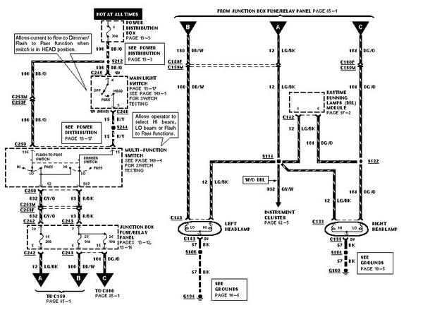
If you bridge circuit 196 and 15 or as you put it terminal #8 and #9 or the dark blue/orange with the red/yellow you will in effect tuen on the headlights permenantly.
If you look closely #8 takes power from the fuse and sends it to#9, the Autolamps, and the multi-function switch which then sends it to the Head Lamps and the Fog lamp switch.
The fog lamp switch works in two ways. First it completes the ground to the Fog Lamp Relay which turns on the Fog Lamps.
Second it acts as a splice to turn on the Fog Lamp on indicator.
It receives power only when the headlights are on and the hi beams are off.
Now the question is when do you want your fogs to go on/off? Do you want them to go on anytime you pull on the switch? Anytime the parking lights are on. Any time the Headlights are on. And do you want them to go off when the Hi beams are on?
Where to bridge the wires is dependant on the answers to the above questions.
Regards
Jean Marc Chartier
PS I know I can manage anytime the switch is pulled. Mine are like that, well almost, long story. I most likely can manage any time the parks and any time the headlights are on regardless of the hi beam position. The rest I will have to look closer at the diagrams.
#11
05-06-2004, 09:10 PM
Join Date: Jan 2004
Location: Chicago, Illinois
Posts: 272
Likes: 0
Received 0 Likes
on
0 Posts
I think I have it pretty well sorted right now. I would never want to bridge the #8 and #9 terminal, since as you said, it would turn the headlights on permanently.
Instead, what I want to do is tap the #8 terminal lead (now confirmed to be a dark blue w/ orange stripe lead) (aka the 196 circuit) and run it to a point at somewhere in the 15 circuit (a red/yellow lead running from the switch terminal #9 to the multi-function switch). I would need to cut the 15 circuit somewhere between the S244 splice junction and connector C259 (the multifunction switch) and splice the end running toward the switch to the 196 circuit. That effectively bypasses the requirement of having the headlamps on to get power to the fog lamp relay fuse (and onwards through the main light switch etc.).
I tried looking under there right now, but its getting kind of dark so I'll have to tackle it on the weekend. My only remaining question is if anyone knows (without ripping their dash apart) where exactly the S244 splice or the C253 connector are located? If I can hook up with one of them, I can make the patch easily.
And thanks again everyone for your help and comments! I love this board!
#12
05-07-2004, 12:53 AM
Not so fast grasshopper. I always wanterd to say that. 
Circuit 15 goes into the multifunction switch as a common wire to the Headlights and Fog lamps. Notice on the Schematic that there is only one wire after the splice going towards the right with the notation Heallights with the applicable page and right below it Fog Lamps with the applicable page. The other wires, middle goes to the Autolamps and the left side one goes to the DRL.
There is more. It comes out of the Multifunction switch as a single wire called cicuit 1033. It then goes to to a connector for the Hi beam interrupt for the DRL and exits as circuit 13, again a single wire. It then goes into the Central Junction Box and splits up into three cuircuits. # 188 for the Fog Lamps, which is the White/Black wire. and circuits 160 & 161 for the left & right headlamp respectivly. Or autolamps if you have that option.
So if you bridge contact #8 circuit to anywhere in circuit 15 you will still permanently turn on the headlights.
JMC
#13
05-07-2004, 10:53 AM
Join Date: Jan 2004
Location: Chicago, Illinois
Posts: 272
Likes: 0
Received 0 Likes
on
0 Posts
So, this circuit 188, which exists somewhere after a splice connection inside the main junction box, is what I should be cutting and splicing to circuit 196 (the #8 terminal on the switch), right? Thanks for the heads up. The diagrams don't show that circuit.
And if that means I'll need to crack open the power dist box in the engine compartment, it sounds like it'd be easier to just throw a 5A fuse in between the 196 circuit and the #2 terminal on the switch. In fact, that is the way I think I'll take this now. No need to start cutting apart the big power box for a simple 5A circuit.
Thanks again!
#14
05-07-2004, 12:40 PM
There is one more thing. Make sure you cut circuit 188 going to the fuse when you bridge it to power from circuit 196. If you do not you wil blow the 5 amp #27 fuse in the Central Junction Box. This fuse is in parrallel with the headlight fuse and when you power circuit 188 it not only goes to the fog lamp relay but it tries to got to the headlights and blows. The headlights have a 10 amp draw. This is the problem people are having. When they turn on the fogs poof...
JMC
JMC
#15
05-07-2004, 01:42 PM
Join Date: Jan 2004
Location: Chicago, Illinois
Posts: 272
Likes: 0
Received 0 Likes
on
0 Posts