Reparing Lighted Switches
#1
 02-04-2009, 06:11 PM


Reparing Lighted Switches
Like many of you, I became frustrated when I discovered that the two power window switches on the passenger side, and the two door lock switches in the front were no longer lighting up. There were posts on replacing LEDs in earlier switches, but nothing about repairing ones in 2004-2008 trucks. I decided to give it a try.
First, you have to get the armrest switch plate off the door. It's easily pried off with a plastic putty knife (if you don't have a trim tool). Disconnect the electrical connectors and remove the switch from the plate - the procedure should be obvious, once you look at what you have to do.
Next, pry the switch rocker cover off the switch. I used a flat-blade screwdriver to do this. Here's what you see now:
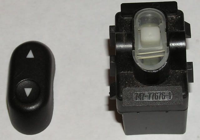
The LEDs shine up through the translucent membrane around the white switch rocker (when they're working, that is).
Now, you'll have to get the black top off the switch housing. I used a flat blade screwdriver to spread the sides of the housing enough to release it. The white rocker, sitting above the circuit board, is exposed now and comes out next.
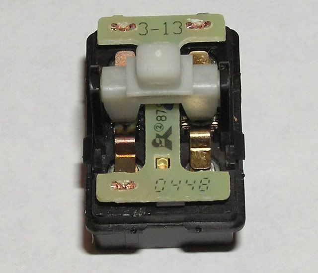
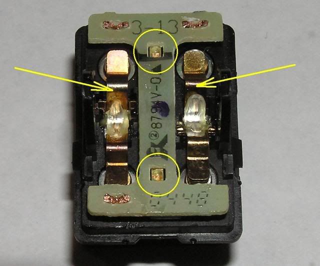
Just pull the sides away from the white rocker ( used my thumbnail) and it will slide out. Now you can see the switch armatures themselves, down on either side of the circuit board pointed to by arrows. I just lifted these out with tweezers. The LEDs are circled and they are TINY - about 1 mm.
Now you have to get the circuit board out of the switch housing. I used a large, flat-bladed screwdriver to pry it up off the three supports that hold it on. At this point, here's what you have:
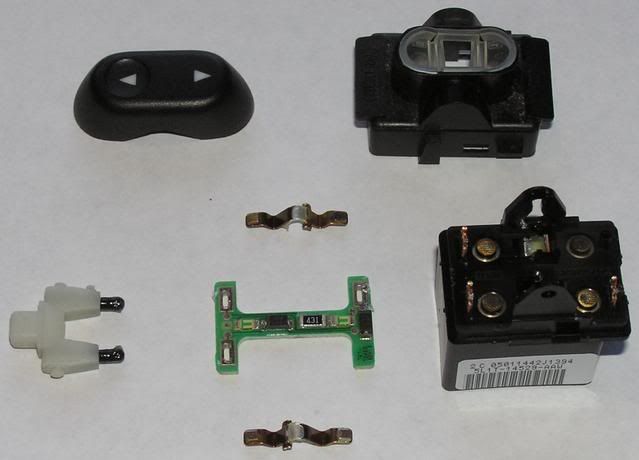
I found the switch contacts were "blackened", probably from arcing, so I burnished them with a typewriter eraser.
Here's a closer look at the underside of the circuit board. I found cracks in the circuit on one or both sides of the 431 ohm resistor in the location pointed to by arrows. They were visible with a 10-power magnifier. The LEDs are wired in series with this resister, so if there's a crack in this circuit, neither LED will light.
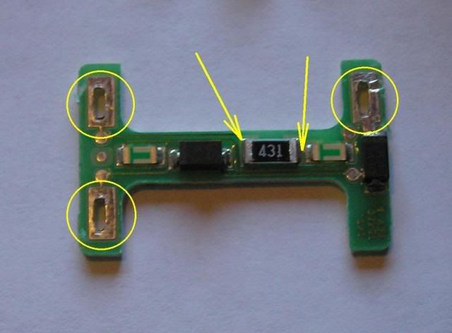
I repaired these cracks with a small piece of #26 copper wire soldered over the crack to bridge it.
Another weakness in the design are the circled rectangular areas. They have to make GOOD mechanical contact with the supports holding the board to the switch housing, because that's the electrical supply.
Once I made the repairs and checked for continuity with an ohmmeter, I reassembled the circuit board onto the switch housing. The circled tabs are what hold the board in place and they have to do it tightly, or you won't get an electrical feed. I used a nail set tapped lightly with a hammer to spread them and hold the board down securely.
I actually considered soldering the board to the supports, but decided against it in case I ever needed to remove the board again.
Finally, we can test the switch in the truck. Thankfully, it can be done as soon as the board is back in place by simply plugging it in to the wire harness as you see here:
With the ignition ON, the LEDs are lit up! I also tried "wiggling" the board on the switch and found I had to tighten two of them down better with more taps from a nail set. I was glad I tested the switch before completely reassembling it!
The rest of the reassembly was the reverse of the disassembly. The door lock switches are quite similar to the window switches, but not quite as complicated.
The whole process took about 2-3 hours to do and now my switches are all lit again.
- Jack
First, you have to get the armrest switch plate off the door. It's easily pried off with a plastic putty knife (if you don't have a trim tool). Disconnect the electrical connectors and remove the switch from the plate - the procedure should be obvious, once you look at what you have to do.
Next, pry the switch rocker cover off the switch. I used a flat-blade screwdriver to do this. Here's what you see now:
The LEDs shine up through the translucent membrane around the white switch rocker (when they're working, that is).
Now, you'll have to get the black top off the switch housing. I used a flat blade screwdriver to spread the sides of the housing enough to release it. The white rocker, sitting above the circuit board, is exposed now and comes out next.
Just pull the sides away from the white rocker ( used my thumbnail) and it will slide out. Now you can see the switch armatures themselves, down on either side of the circuit board pointed to by arrows. I just lifted these out with tweezers. The LEDs are circled and they are TINY - about 1 mm.
Now you have to get the circuit board out of the switch housing. I used a large, flat-bladed screwdriver to pry it up off the three supports that hold it on. At this point, here's what you have:
I found the switch contacts were "blackened", probably from arcing, so I burnished them with a typewriter eraser.
Here's a closer look at the underside of the circuit board. I found cracks in the circuit on one or both sides of the 431 ohm resistor in the location pointed to by arrows. They were visible with a 10-power magnifier. The LEDs are wired in series with this resister, so if there's a crack in this circuit, neither LED will light.
I repaired these cracks with a small piece of #26 copper wire soldered over the crack to bridge it.
Another weakness in the design are the circled rectangular areas. They have to make GOOD mechanical contact with the supports holding the board to the switch housing, because that's the electrical supply.
Once I made the repairs and checked for continuity with an ohmmeter, I reassembled the circuit board onto the switch housing. The circled tabs are what hold the board in place and they have to do it tightly, or you won't get an electrical feed. I used a nail set tapped lightly with a hammer to spread them and hold the board down securely.
I actually considered soldering the board to the supports, but decided against it in case I ever needed to remove the board again.
Finally, we can test the switch in the truck. Thankfully, it can be done as soon as the board is back in place by simply plugging it in to the wire harness as you see here:
With the ignition ON, the LEDs are lit up! I also tried "wiggling" the board on the switch and found I had to tighten two of them down better with more taps from a nail set. I was glad I tested the switch before completely reassembling it!
The rest of the reassembly was the reverse of the disassembly. The door lock switches are quite similar to the window switches, but not quite as complicated.
The whole process took about 2-3 hours to do and now my switches are all lit again.
- Jack

#3
02-04-2009, 06:53 PM

Member
Join Date: Oct 2008
Location: Ontario
Posts: 34
Likes: 0
Received 0 Likes
on
0 Posts
#4
02-04-2009, 10:25 PM
Thank you, gentlemen! It wasn't that much work, once I figured out the problem. I found that the door lock switches run about $20 apiece. I haven't found a price for the window switches, but they are more complicated and must cost more.
And - I'd be afraid of getting some with the same defects. I feel pretty confident in my repair. We'll see how it holds up.
- Jack
And - I'd be afraid of getting some with the same defects. I feel pretty confident in my repair. We'll see how it holds up.
- Jack


#6
02-05-2009, 12:18 PM

Thank you, gentlemen! It wasn't that much work, once I figured out the problem. I found that the door lock switches run about $20 apiece. I haven't found a price for the window switches, but they are more complicated and must cost more.
And - I'd be afraid of getting some with the same defects. I feel pretty confident in my repair. We'll see how it holds up.
- Jack
And - I'd be afraid of getting some with the same defects. I feel pretty confident in my repair. We'll see how it holds up.
- Jack
Jack,
I had to replace my master power window switch on my 2006 already ( water from snow falling in on it ) and it was $ 38.04 from www.oemfordparts.com when I ordered it ( p/n : 5L1Z-14529-AA ). Add to this 9.50 in S/H.
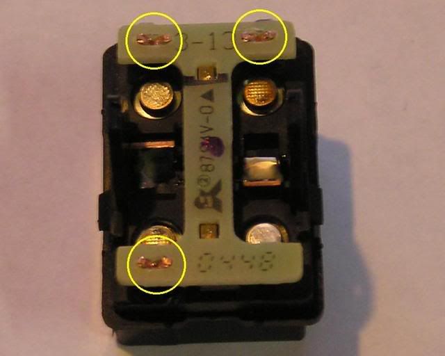
I just took apart my old one to take some quick pictures of it.
the LED board is soldered onto the housing, rather then the type that you show on the power door lock. Bit different layout, but the same design.

Red circle is the solder joints for powering the LEDS, and the LEDs are circled in blue.
Thanks for starting this thread, might want to have RP make it a sticky at the top.
Last edited by SSCULLY; 04-25-2009 at 07:33 PM.
#7
02-05-2009, 04:24 PM
Thanks for the link, SSCULLY, and thanks for the part number. That unit is a lot cheaper than I thought it would be!
You may want to correct your description to say the LEDs are circled in blue, but it's a great picture. Bummer, in a way that the board is soldered to the switch housing, but I bet that removes one of the weaknesses in the design of my switches. However, if any of the circuits develop hairline fractures, good luck on getting in there to fix them!
I didn't take my master switch out, since all the LEDs in it are working. I wonder if it's the same design as yours?
- Jack
Trending Topics
#8
02-05-2009, 05:57 PM
..<snip>...Bummer, in a way that the board is soldered to the switch housing, but I bet that removes one of the weaknesses in the design of my switches. However, if any of the circuits develop hairline fractures, good luck on getting in there to fix them! ..<snip>...
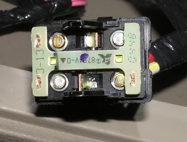
There are even test points in the traces, about the size of a meter probe.
This one, no need to take it out, but I guess if you wanted to, some solder rope and a good iron, it would be out in 2 min flat.

You can see the same discoloration on the switch contacts, that your power lock has in this close up as well.
Quick test on this one is + and gnd to the 2 solder points, and all the lights should light. The test points would give you the ability to find the problem path to fix it, if the need ever arises.
Thanks for pointing that out, got the text correct.
Last edited by SSCULLY; 04-25-2009 at 07:33 PM.
#9
02-05-2009, 08:06 PM
Excellent addition, Sir, as always!  Nice to know the circuits are all on the "exposed" side. Now I don't have to worry about problems with that unit.
Interestingly, I went to the link you gave (which is Southwest Ford) and I simply cannot find the switch. With the part number you listed, I found it in two or three other sources, but at a higher price - $46-$49 as I recall.
Just looking at the new picture you posted, since there are four pairs of LEDs, it looks like they may ALL be wired in series, eliminating the need for a voltage dropping resistor, and, if they ALL go out, you know what the problem is!
I PM'd Rockpick about a sticky status too, thanks for the suggestion.
Nice to know the circuits are all on the "exposed" side. Now I don't have to worry about problems with that unit.Interestingly, I went to the link you gave (which is Southwest Ford) and I simply cannot find the switch. With the part number you listed, I found it in two or three other sources, but at a higher price - $46-$49 as I recall.
Just looking at the new picture you posted, since there are four pairs of LEDs, it looks like they may ALL be wired in series, eliminating the need for a voltage dropping resistor, and, if they ALL go out, you know what the problem is!
I PM'd Rockpick about a sticky status too, thanks for the suggestion.
#10
02-05-2009, 08:19 PM

Senior Member
Join Date: Jun 2007
Location: SCPA
Posts: 225
Likes: 0
Received 0 Likes
on
0 Posts
#11
02-05-2009, 08:29 PM
Jack - Excellent post, sir. Thanks for the contribution to the site.
Rather than sticky'ing it within the electrical forum, I'm going to utilize our 'How-To' forum for this post...
It's my hope that we can continually build the How-To forum with EXCELLENT threads such as this one...
Naturally, I'll leave this one in-situ too...
Thanks again for your contribution!!!!
-RP-
#12
02-05-2009, 08:41 PM
I'll sent an email to Keith Sexton and asked for the web site that is the interface to the trademotion site
www.southwestfordparts.com.
I always had the best prices and turn around time on parts from them, that is why I used them all the time, after Keith Starr closed up the site in CA some time ago.
Tasca has it for the range you quoted 42.48.
I looked back, and in Jun-07, the list price was 6.00 lower. So a 4.00 increase is not out of line.
Last edited by SSCULLY; 02-06-2009 at 07:05 PM.
#13
02-06-2009, 12:16 PM
Senior Member
Join Date: Jun 2007
Location: SCPA
Posts: 225
Likes: 0
Received 0 Likes
on
0 Posts
I just fixed all my switches! I ran new solder across the old or used the solder sucker and removed all the old solder and it worked great! I also found that if you are fixing the rear window slider, when you take the whole assembly down, to get to the switch you will need a torx 10 to remove four of the five screws. Hemostats work great for holding things and prying up the board.
#14
02-06-2009, 07:03 PM
Good on ya mate! I used a clamping pair of tweezers (long and skinny) to hold the little wire pieces to the damaged circuits as I soldered them in. Guess I COULD have added that detail. :o I'm sure just adding solder to bridge the crack will do wonders though.
I don't know about the rest of you, but like j2h1, I suspect, I get a great deal of satisfaction out of reworking some piece of shoddily made, or badly designed equipment to make it better.
- Jack
I used a clamping pair of tweezers (long and skinny) to hold the little wire pieces to the damaged circuits as I soldered them in. Guess I COULD have added that detail. :o I'm sure just adding solder to bridge the crack will do wonders though. I don't know about the rest of you, but like j2h1, I suspect, I get a great deal of satisfaction out of reworking some piece of shoddily made, or badly designed equipment to make it better.
- Jack
#15
02-06-2009, 08:17 PM

Now that i have blue lights in the dash, i really hate the green switches.
Nice thread Jack, I will probably go in and replace the LEDs with blue ones now thaanks to your detailed pics.
If anyone has them apart, can you run a meter on the LED cirrcuit and see how much voltage the LEDs are recieving.
Nice thread Jack, I will probably go in and replace the LEDs with blue ones now thaanks to your detailed pics.
If anyone has them apart, can you run a meter on the LED cirrcuit and see how much voltage the LEDs are recieving.