2004 F150; How to replace ball joints and coil-over shocks.
#1
 07-05-2011, 11:21 PM


Join Date: Jun 2009
Location: Easton, MA
Posts: 215
Likes: 0
Received 0 Likes
on
0 Posts
2004 F150; How to replace ball joints and coil-over shocks.
Hi Guys,
With 94k miles and a broken front coil, I decided it was time to replace these parts.
First and foremost I want to thank John Benoit for his excellent write-up on replacing these.
I am NOT trying to outdo his efforts, but just give you some pictures to go on... more information to help anyone who needs it.
His write up is here;
https://www.f150online.com/forums/20...-provided.html
Since I had never done ball joints I also viewed this;
http://www.youtube.com/watch?v=v3BlDZdwyt8
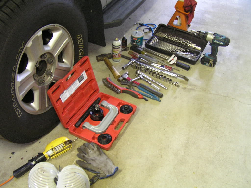
Tools used
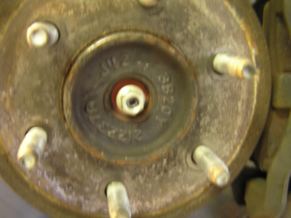
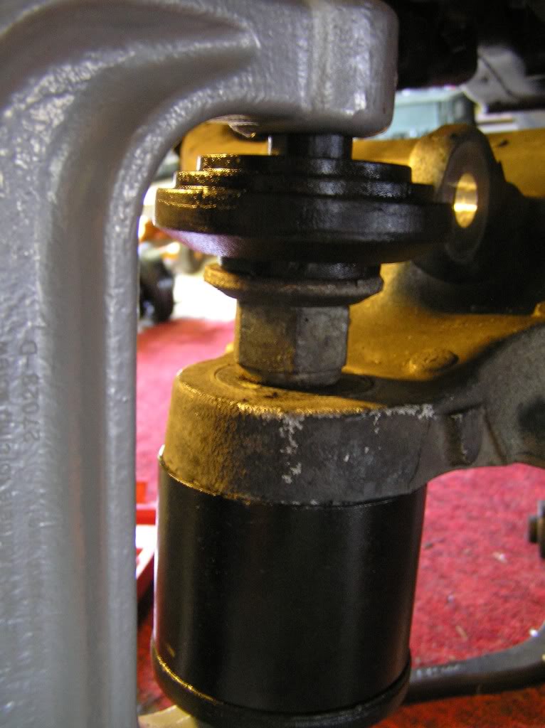
With truck supported under frame, and wheel removed, remove this bearing cap.
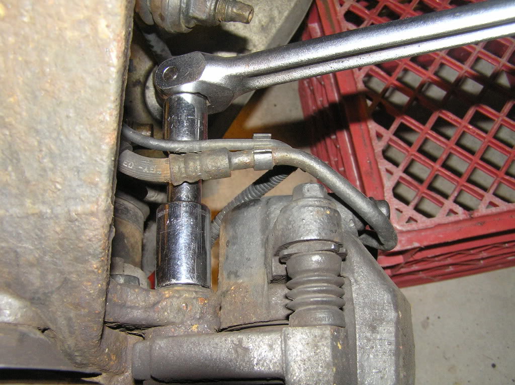
Next remove the small nut....
Remove the caliper mounting bolts (have something ready to place the caliper on, or a means of securing it up) a milk-crate works well...
Remove the rotor too and set aside...
Next remove the 4wd vacuum lines....
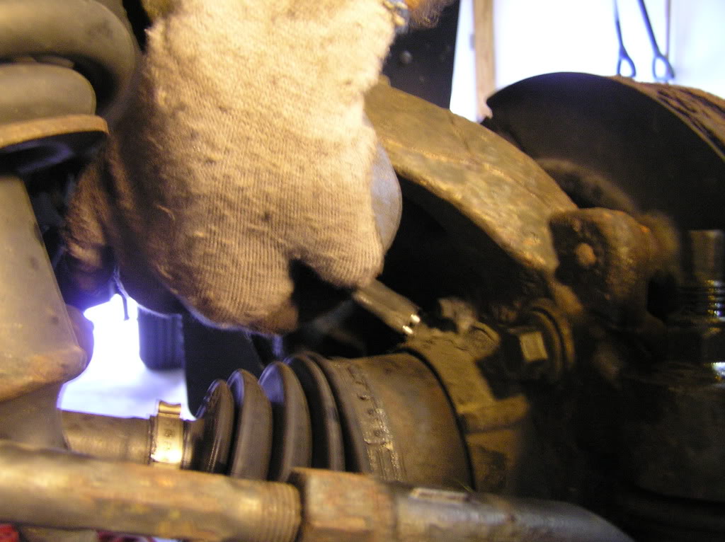
Now the anti-lock brake sensor....
This pulls straight out, I had to twist, pry, curse, lubricate, curse,...
(one side came out in seconds, one took ten minutes!)
>>>If you are NOT replacing the upper control arms, the next step will need to be done without damage to it.<<<
Since this just makes the job more time consuming, plan on replacing these.
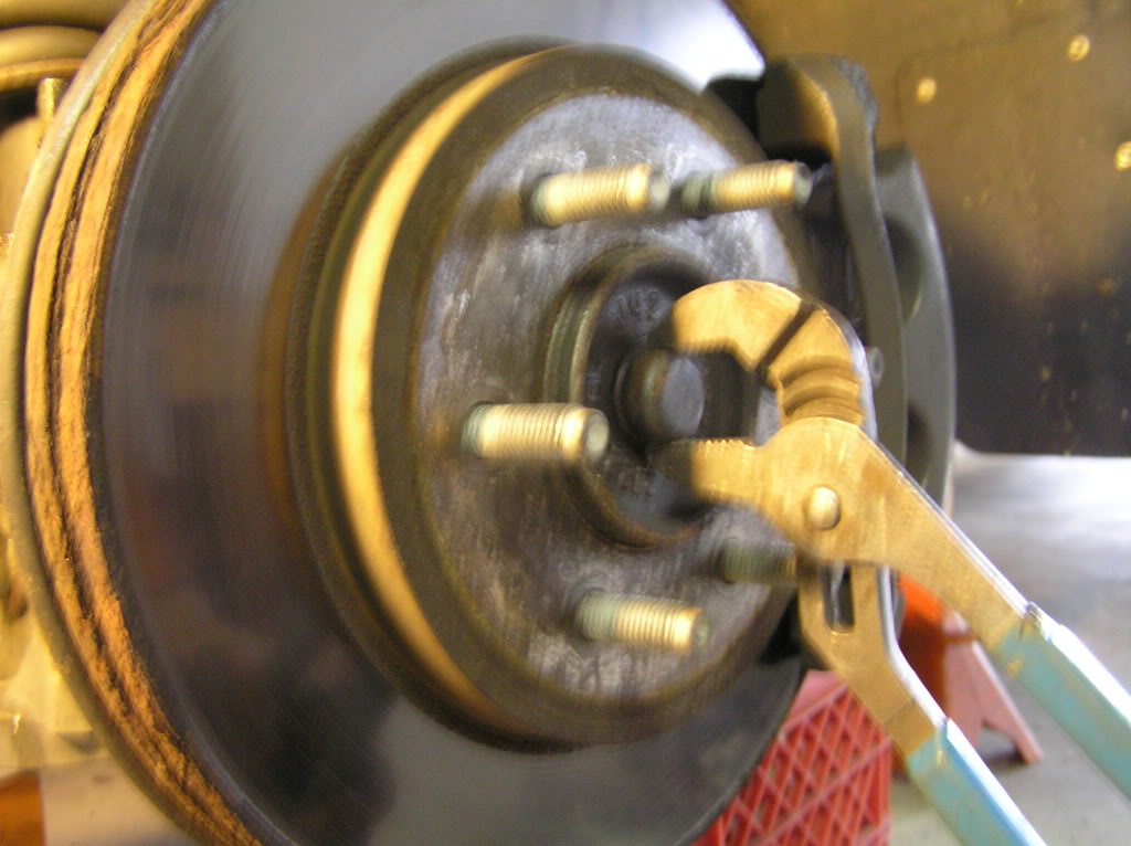
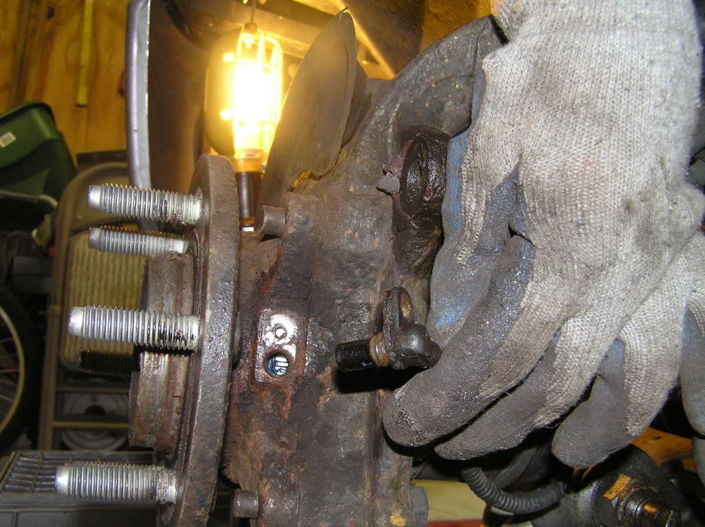
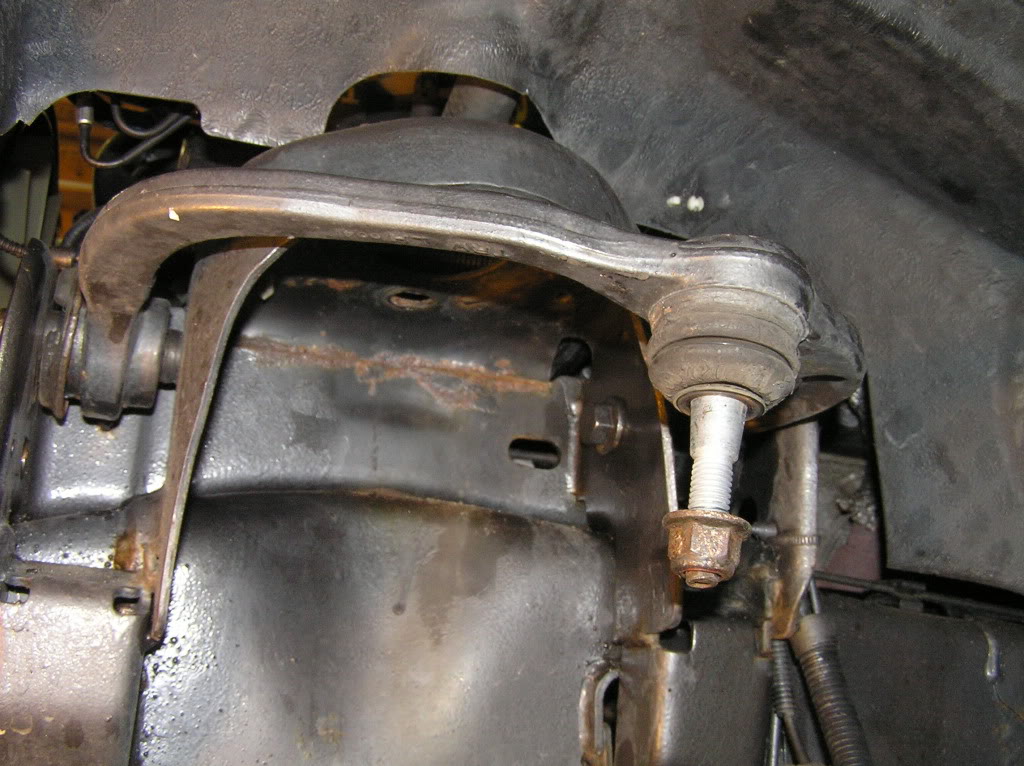
Remove the upper ball joint nut.
Beat the stem-end till the ball joint pops out, or a few whacks on the cast spindle arm may do the trick (like in the video).
>>>After this separates, push the stem back through and put the nut back on with a few turns, (it helps hold the spindle from falling on you after the next few steps).<<<
(In this pic it's been loosened and put back through.)
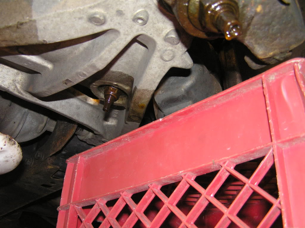
To replace the shock and spring assembly, the lower control arm needs to be lowered more than what the stabilizer bar link will allow;
To gain the needed access, the link mounting nut needs to be removed from UNDER the lower control arm....
Next remove the steering tie-rod end nut and free this from the spindle.
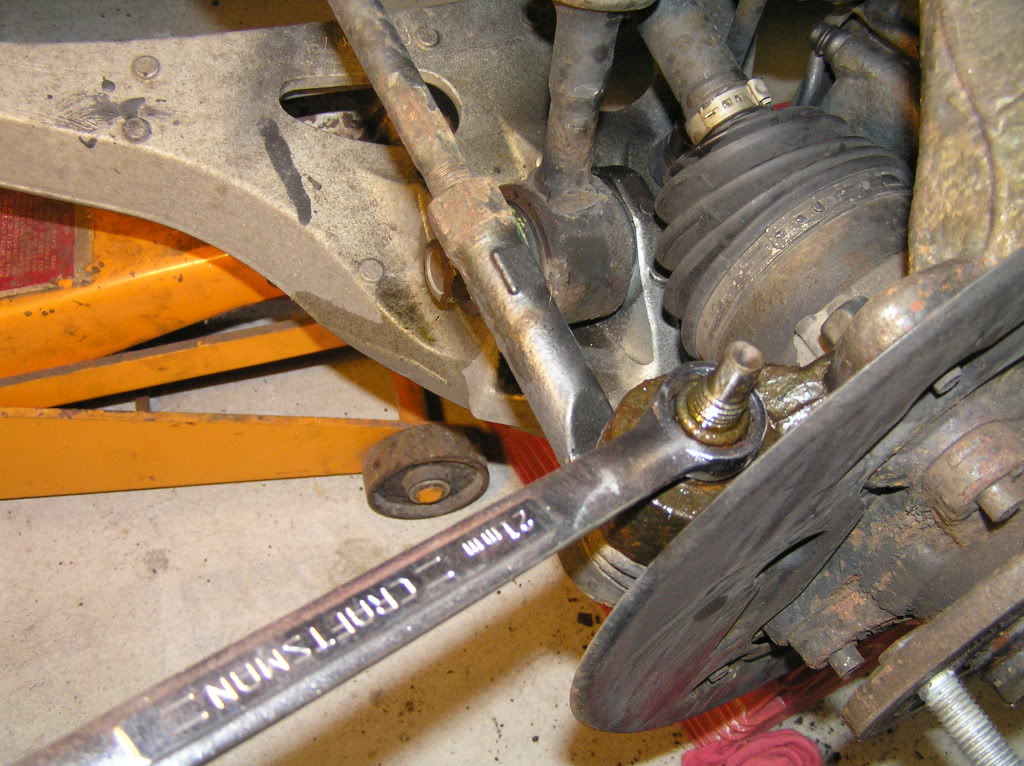
Now remove the lower ball joint nut, and separate/ free the spindle from it.
>>>At this point the only thing holding the spindle should be the upper control arm nut.<<<
Grab the spindle tightly, & remove the upper nut,... the spindle comes off towards you, as it drops off of the lower ball joint.
Set this aside....
Next, bungee or tie the drive shaft aside....
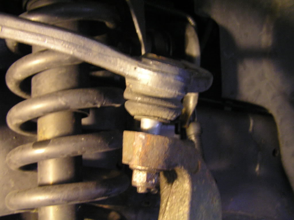
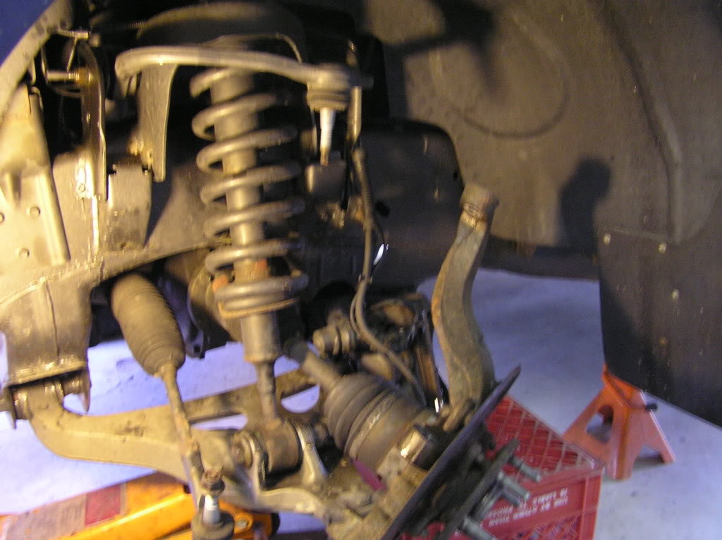
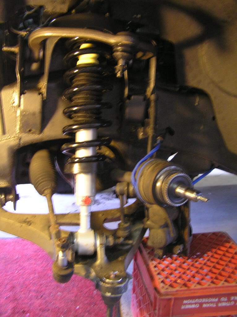
The shock/coil-over is replaced by removing the three nuts at the top...
>>>>NOT THE CENTER NUT....WHICH LETS THE SPRING FLY<<<<
and the big bottom bolt.
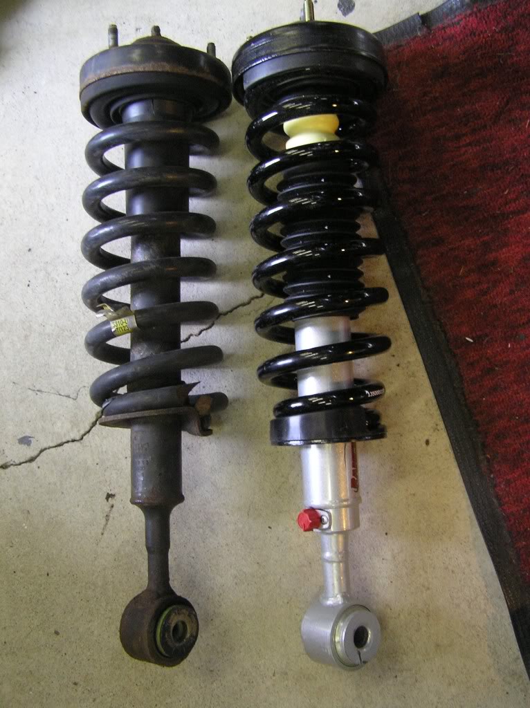
Here's the new and old...
Important.....
>>>> Before removing the upper control arms, measure the angle that they are sitting at. The new upper control arms need to be installed and tightened at the same angle, to prevent binding or tearing of the inner rubber mounts, once everything is back together.<<<<
Old upper arm....
New upper arm....
Next the lower ball joint gets pressed out downward with the rented press.
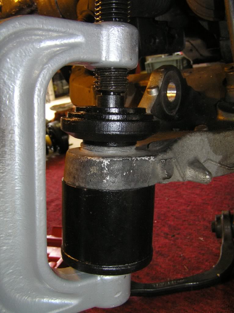
You can see that this is going to bottom-out before the ball joint is all the way through....I inverted the big-*** nut from the shock, and used it to push the ball joint the rest of the way.
Now the new ball joint gets pressed in....
You will need TWO of the 2" sleeves, one to push up on the metal rim of the new ball joint, and one to allow clearance for the ball joint to pass 1/4 inch or so above the lower control arm.

Be sure to put the lock-ring on the upper side, along with the new grease fitting.
Now the new coil-over got put in...
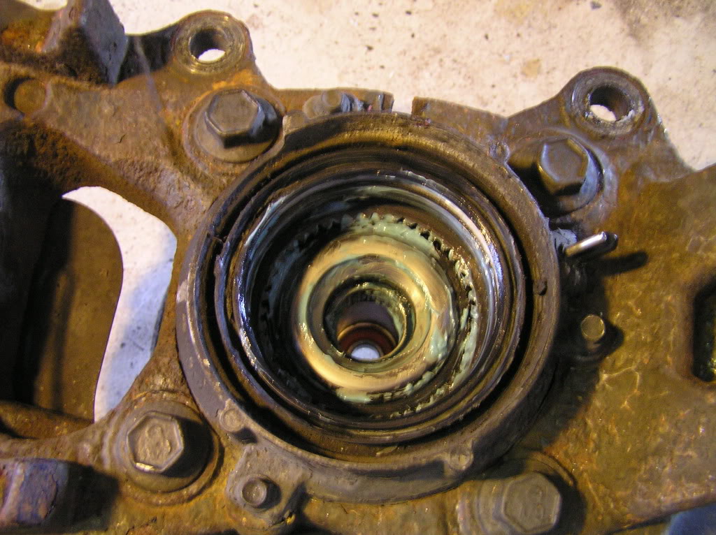
Next I cleaned and re-greased the 4wd engagement-gears and
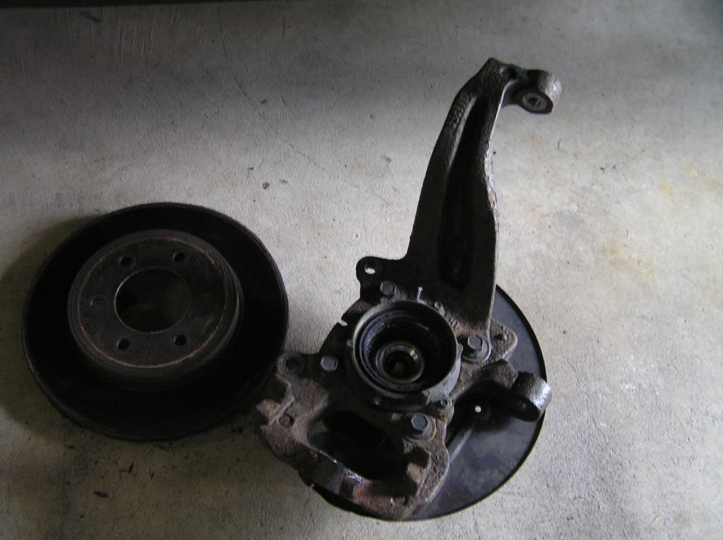
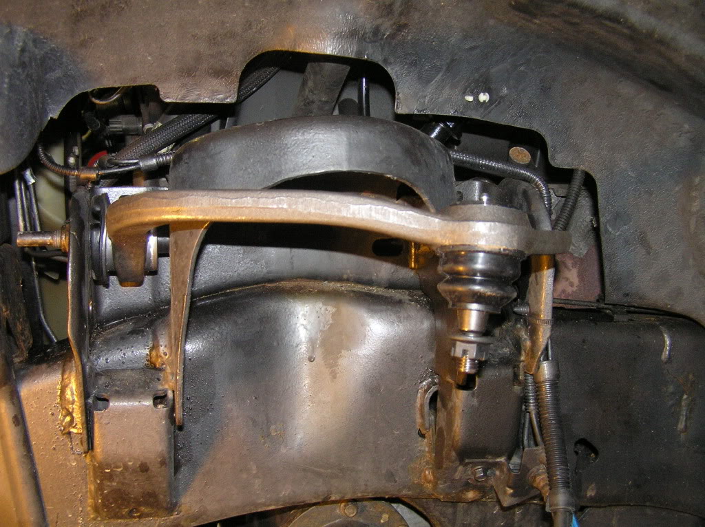
reinstalled the spindle....
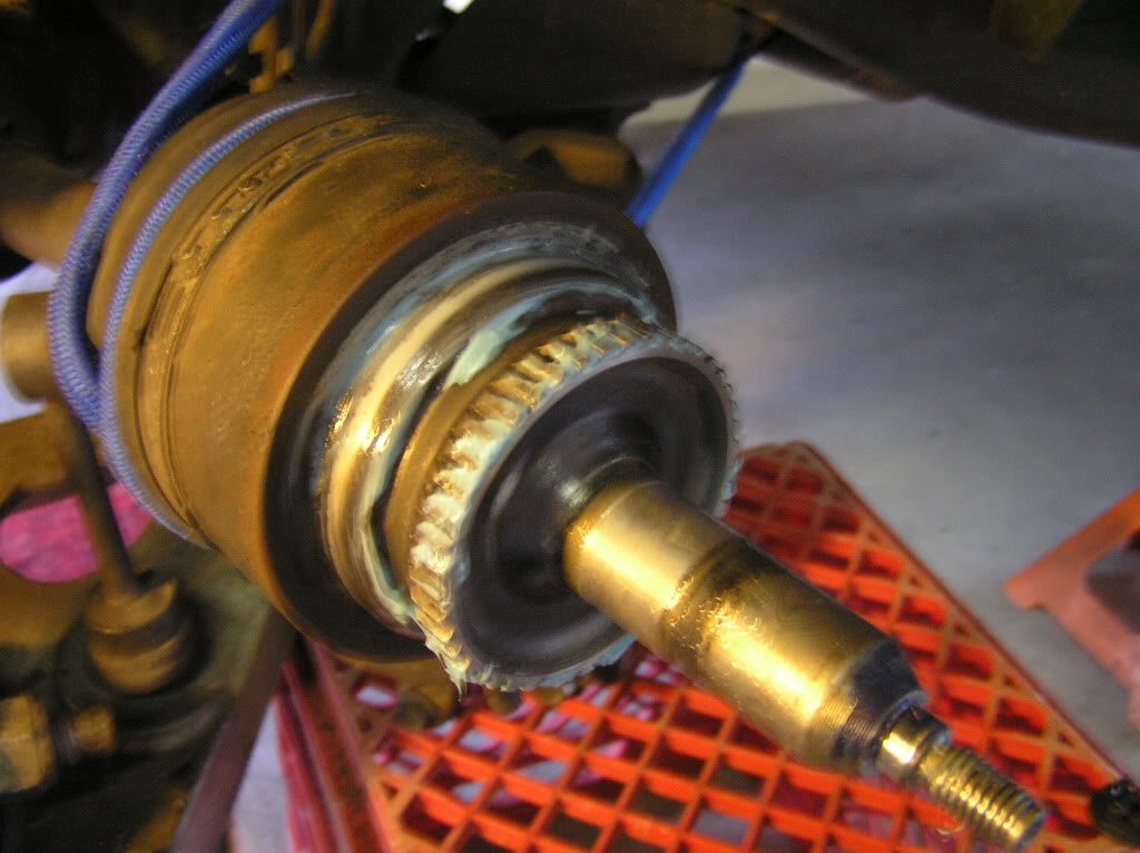
The spindle installs upwards over the lower ball joint (slip the drive shaft in at this time,& make sure it fully seats).
Getting the bottom nut started helps support the spindle.
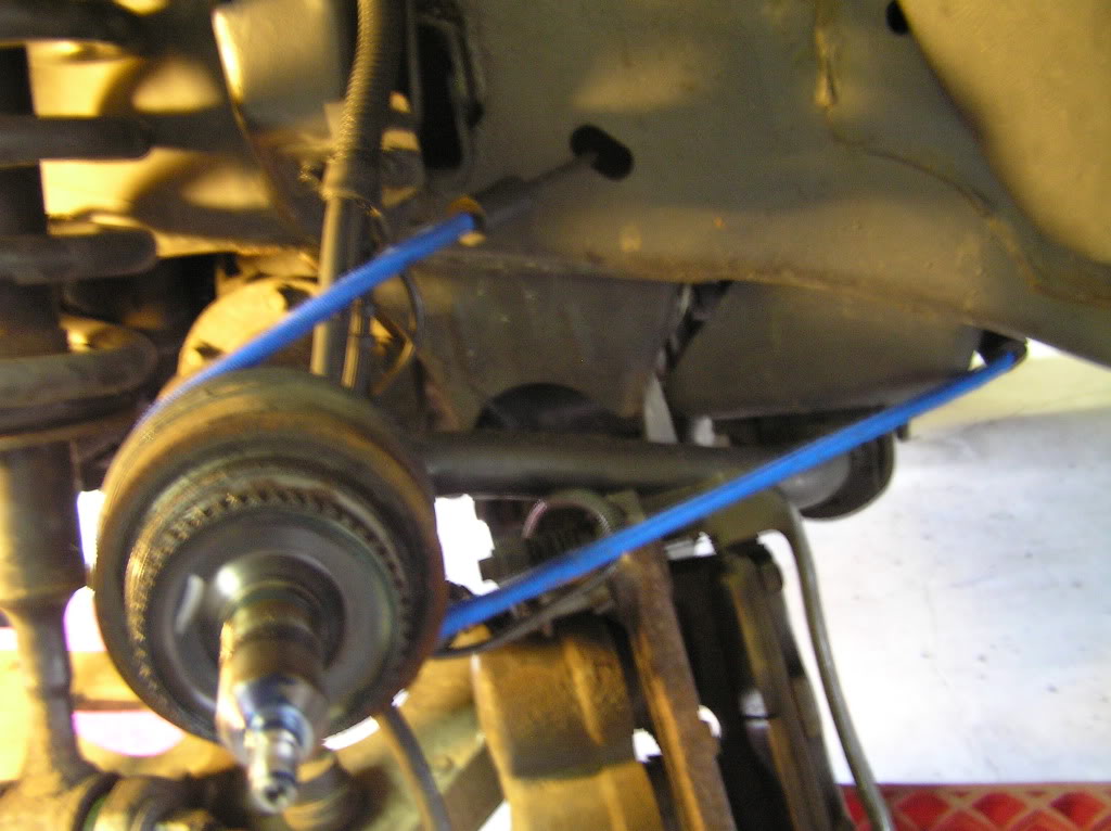
Grab a pry-bar and push the upper control arm down to get the upper ball joint into place, get the upper castle nut started.
Set the tie-rod end, stabilizer bar end-link nut, drive-axle nut, & cap.
Dang, only pic I forgot to take....everything buttoned up.
Make sure to re-install the anti-lock brake sensor and 4wd vacuum lines before replacing the rotor.
Re-install the caliper.
Also very important;
>>>> Make sure you tighten all of your hardware to the proper torque specifications.<<<<
Add the cotter-pin to your ball joints if so equipped, and a few pumps of grease.
Good Luck
MB
With 94k miles and a broken front coil, I decided it was time to replace these parts.
First and foremost I want to thank John Benoit for his excellent write-up on replacing these.
I am NOT trying to outdo his efforts, but just give you some pictures to go on... more information to help anyone who needs it.
His write up is here;
https://www.f150online.com/forums/20...-provided.html
Since I had never done ball joints I also viewed this;
http://www.youtube.com/watch?v=v3BlDZdwyt8
Tools used
With truck supported under frame, and wheel removed, remove this bearing cap.
Next remove the small nut....
Remove the caliper mounting bolts (have something ready to place the caliper on, or a means of securing it up) a milk-crate works well...
Remove the rotor too and set aside...
Next remove the 4wd vacuum lines....
Now the anti-lock brake sensor....
This pulls straight out, I had to twist, pry, curse, lubricate, curse,...
(one side came out in seconds, one took ten minutes!)
>>>If you are NOT replacing the upper control arms, the next step will need to be done without damage to it.<<<
Since this just makes the job more time consuming, plan on replacing these.
Remove the upper ball joint nut.
Beat the stem-end till the ball joint pops out, or a few whacks on the cast spindle arm may do the trick (like in the video).
>>>After this separates, push the stem back through and put the nut back on with a few turns, (it helps hold the spindle from falling on you after the next few steps).<<<
(In this pic it's been loosened and put back through.)
To replace the shock and spring assembly, the lower control arm needs to be lowered more than what the stabilizer bar link will allow;
To gain the needed access, the link mounting nut needs to be removed from UNDER the lower control arm....
Next remove the steering tie-rod end nut and free this from the spindle.
Now remove the lower ball joint nut, and separate/ free the spindle from it.
>>>At this point the only thing holding the spindle should be the upper control arm nut.<<<
Grab the spindle tightly, & remove the upper nut,... the spindle comes off towards you, as it drops off of the lower ball joint.
Set this aside....
Next, bungee or tie the drive shaft aside....
The shock/coil-over is replaced by removing the three nuts at the top...
>>>>NOT THE CENTER NUT....WHICH LETS THE SPRING FLY<<<<
and the big bottom bolt.
Here's the new and old...
Important.....
>>>> Before removing the upper control arms, measure the angle that they are sitting at. The new upper control arms need to be installed and tightened at the same angle, to prevent binding or tearing of the inner rubber mounts, once everything is back together.<<<<
Old upper arm....
New upper arm....
Next the lower ball joint gets pressed out downward with the rented press.
You can see that this is going to bottom-out before the ball joint is all the way through....I inverted the big-*** nut from the shock, and used it to push the ball joint the rest of the way.
Now the new ball joint gets pressed in....
You will need TWO of the 2" sleeves, one to push up on the metal rim of the new ball joint, and one to allow clearance for the ball joint to pass 1/4 inch or so above the lower control arm.
Be sure to put the lock-ring on the upper side, along with the new grease fitting.
Now the new coil-over got put in...
Next I cleaned and re-greased the 4wd engagement-gears and
reinstalled the spindle....
The spindle installs upwards over the lower ball joint (slip the drive shaft in at this time,& make sure it fully seats).
Getting the bottom nut started helps support the spindle.
Grab a pry-bar and push the upper control arm down to get the upper ball joint into place, get the upper castle nut started.
Set the tie-rod end, stabilizer bar end-link nut, drive-axle nut, & cap.
Dang, only pic I forgot to take....everything buttoned up.
Make sure to re-install the anti-lock brake sensor and 4wd vacuum lines before replacing the rotor.
Re-install the caliper.
Also very important;
>>>> Make sure you tighten all of your hardware to the proper torque specifications.<<<<
Add the cotter-pin to your ball joints if so equipped, and a few pumps of grease.
Good Luck
MB
#2
07-06-2011, 06:37 AM
Join Date: Jun 2009
Location: Easton, MA
Posts: 215
Likes: 0
Received 0 Likes
on
0 Posts
Thank You KC8FLB for providing this torque spec list.....
Torque Specifications
base, 5.4L Description Nm lb-ft
Wheel nuts 204 150
Jounce bumper-to-frame bolt 35 26
Wheel hub-to-wheel knuckle 200 148
Tie-rod end nut 150 111
ront axle-to-wheel hub nut 27 20
Upper ball joint nut 115 85
Upper arm-to-frame nuts 150 111
Lower ball joint nut 150 111
Lower arm-to-frame bolt and 300 222
Front shock absorber rod nut, 30 22
Item Specification Shock absorber upper 48 35
Shock absorber-to-lower arm 475 351
Wheel Track Stabilizer bar bracket-to-frame 48 35
bolts
Stabilizer bar-to-link nut 133 98
Stabilizer bar-to-link to lower 90 66
control arm nut
Anti-lock brake sensor bolt 18 13
2004 F150, 12/2003
204-00-4 Suspension System 204-00-4
SPECIFICATIONS (Continued)
Torque Specifications (Continued) Torque Specifications (Continued)
Description Nm lb-ft Description Nm lb-ft
Integrated wheel end bolt (3 12 9 Shock absorber, lower 90 66
required) Rear caliper bolts 32 24
Caliper anchor plate-to-wheel 200 148 U-bolt nuts (light duty) 115 85
knuckle bolts
U-bolt nuts (heavy duty) 250 184
Caliper-to-anchor plate bolts 32 24
Spring/frame nut (front) 300 222
Rear Suspension
Spring/shackle nut (rear) 133 98
Shock absorber, upper 90 66
Spring shackle/frame nut 133 98
2004
#3
07-06-2011, 10:52 AM
No problem. I am actually in the middle of this same job. My 2004 has 120k miles on it and this is what I am halfway in the middle of installing:
bilstein 5100 rear shocks
New made from scratch driveshaft to fix bad u-joints (u-joints not replaceable on 2004)
Bilstein 5100 front shocks
New moog upper control arms with new balljoints
New moog lower balljoints
New moog steering tie rod ends
New moog stabilizer bar links
New IWE vaccuum actuators (they were "frozen")
Went from zero grease fittings to 10 grease fittings....
Hopefully this should last me another 120K miles.
Should have it back together today and hopefully a full chassis alignment done tomorrow.

#5
08-06-2011, 06:06 AM
Join Date: Jun 2009
Location: Easton, MA
Posts: 215
Likes: 0
Received 0 Likes
on
0 Posts
Those are Rancho Quick-lifts...
http://www.rockauto.com/catalog/raframecatalog.php
Part number RS999909.
They also sell some lesser-expensive, loaded (with spring), front shocks from LeaCree and Monroe.
http://www.rockauto.com/catalog/raframecatalog.php
Part number RS999909.
They also sell some lesser-expensive, loaded (with spring), front shocks from LeaCree and Monroe.
Last edited by mjb1032; 08-06-2011 at 06:08 AM.
#6
08-06-2011, 09:27 PM

Senior Member
Those are Rancho Quick-lifts...
http://www.rockauto.com/catalog/raframecatalog.php
Part number RS999909.
They also sell some lesser-expensive, loaded (with spring), front shocks from LeaCree and Monroe.
http://www.rockauto.com/catalog/raframecatalog.php
Part number RS999909.
They also sell some lesser-expensive, loaded (with spring), front shocks from LeaCree and Monroe.
#7
08-07-2011, 06:26 AM
Join Date: Jun 2009
Location: Easton, MA
Posts: 215
Likes: 0
Received 0 Likes
on
0 Posts
These aren't height adjustable.
Bilstein 5100's are;
http://cart.bilsteinus.com/product/24-122986/1422751
Bilstein 5100's are;
http://cart.bilsteinus.com/product/24-122986/1422751
Trending Topics
#8
10-22-2011, 11:55 PM

#9
10-24-2011, 06:26 AM
Join Date: Jun 2009
Location: Easton, MA
Posts: 215
Likes: 0
Received 0 Likes
on
0 Posts

#11
01-09-2012, 06:21 AM
Join Date: Jun 2009
Location: Easton, MA
Posts: 215
Likes: 0
Received 0 Likes
on
0 Posts

#12
03-25-2012, 08:23 PM

Senior Member
nice write up mjb1032...came in helpful...did upper and lower ball joints on my 05 FX4 today...somethings I differently then the video and the write up...video shows you unbolting the half shaft from the carrier...don't bother...you'll see mj 1032 didn't do that either...it's not necessary...half shaft will not be in the way...now...the abs sensor...I could not get mine to pull out after removing the bolt...so a easier way to do it is follow the wire up to the top of your inner fender well...at the top of the fender well there is a plug on it...just up plug it and put the wire aside...mjb said he rented a ball joint press and used two 2 inch sleeves to press the new ball joint in...I rented a ball joint press also from autozone...my kit only had one 2 inch sleeve...that is all that is necessary...set up the press like he has in the above pictures...once you get the new ball joint started...take the press off...remove the boot off your new ball joint...put the bottom of the press right to the bottom of the ball joint and use the sleeve on top to create the necessary room for the ball joint to press into its place...last thing I did differently...the sway bar end link...don't even bother lossening it...I was able to remove and reinstall my coil over strut without touching the sway bar end link...takes a little musceling but very doable...and that's even with the extra space missing for me because of my spacer for my 2 inch leveling kit...this is the first time I have done ball joints in probably over 10 years...my first side took me about 3 hours...I know that's slow...other side...a hour and twenty minutes...it goes fast when you have done it once and have the exact tools you need laying out...
#13
09-16-2012, 08:17 PM

Senior Member
Join Date: Mar 2004
Location: Washington
Posts: 112
Likes: 0
Received 0 Likes
on
0 Posts
Thanks fellas, used your writeup, and advise and tackled this job yesterday. Took me about 6 hours from beginning jacking the truck up to final clean up complete. What a pain in the rear....but very doable after reading this and other threads.
I replaced the upper and lower ball joints, and finally added the AS 2.5" spacer that I purchased about 4 years ago at the same time.
Wish I would have bought outer tie rods for replacement as well...they are complete junk. I also broke a sway bar end link (my fault for using impact gun and not watching). Was able to get the sway bar end links from NAPA so I could get the girl home safely, but waiting on the tie rods to come in tomorrow morning before alignment
Even pre-alignment and pre-tie rods, what a world of difference already on the short drive home! Who would of thought everything would be that worn out with only 69,000 miles on the girl.
#14
03-06-2013, 10:23 PM

#15
03-09-2013, 01:09 PM

Member
Join Date: Dec 2012
Location: Illinois / California
Posts: 48
Likes: 0
Received 0 Likes
on
0 Posts
I am doing upper control arms and lower ball joint replacements on my '04
f150 4wd. My question is, do you have to torque down both torque values as shown on the torque specs. given? example: tie rod end nut 150 111.... does this mean you're torquing to 150ft lbs. then to 111ft. lbs????
f150 4wd. My question is, do you have to torque down both torque values as shown on the torque specs. given? example: tie rod end nut 150 111.... does this mean you're torquing to 150ft lbs. then to 111ft. lbs????

