Overhead Console Temp Display Repair
#76
 05-22-2011, 12:55 PM


Member
Join Date: Nov 2010
Location: The Devil's Playground
Posts: 35
Likes: 0
Received 0 Likes
on
0 Posts
Great info and had mine completly apart as pictured yet I didn't see this thread until i reinstalled.. Quick pull down again.. but.. have a querie/question? In your picture of the LCD display near the -188/top left corner of the glass display pad, did you notice or anyone else ..a darkened /blackened area in the display? I assumed it may have had a internal short between the layers of the glass display in that area and is the size of a shirt button. Just wodering..and it sort of looks as though it may be blackened in your picture. If you or anyone else can confirm, would be appreciated..
Thanks.
Thanks.
However, to me, if it was something that blew and caused that then i don't think simply re-soldering on a resistor would fix the system. That's why I think its factory.

#77
05-22-2011, 03:51 PM

Junior Member
Join Date: May 2011
Location: Manitoba, Canada
Posts: 3
Likes: 0
Received 0 Likes
on
0 Posts
Yup, mine was like that too. I have a feeling it might be like that from the factory, but who knows...then again, we are all here reading this because we needed to fix our units, so maybe it was something that "blew" and caused it.
However, to me, if it was something that blew and caused that then i don't think simply re-soldering on a resistor would fix the system. That's why I think its factory.
However, to me, if it was something that blew and caused that then i don't think simply re-soldering on a resistor would fix the system. That's why I think its factory.


#79
06-03-2011, 03:00 PM

Member
Join Date: Apr 2011
Location: Vassalboro, ME
Posts: 39
Likes: 0
Received 0 Likes
on
0 Posts
I did this repair yesterday, works great
I can add that mine has the same blacked corner of the display, and after checking with an ebay seller who does these repairs for $30 a pop (plus shipping) it is standard to have that black splotch in the corner, it's where the factory seals the display.
Now, perhaps I missed it, this thread doesn't address how to set your Zone or how to calibrate the compass once you've done the repair.
From my 2003 FSM, here is the chart for the zones:
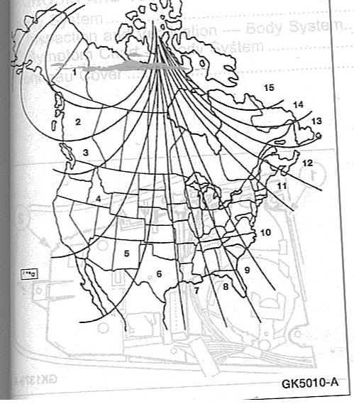
So in order to set your zone, press and hold your mode button until VAR illuminates on the screen. You then can switch to another zone by hitting the mode button again, and cycling through the zones. I am in Zone 11 in Maine, but upon getting my compass working again it was set to zone 4. (odd because the truck was built in VA, sold in MA, but set to a western zone)
Once your zone is set, you can also calibrate your compass. Calibration is activated by pressing and holding the mode button, like I explained in setting your zone. You just have to hold it longer, until it changes from VAR to CAL) You can exit the calibration at any time by removing your key from the ignition. Once CAL is lit, per the FSM- drive in a circle below 5 kmh / 3mph on a level surface away from large metallic structures. (I used a parking lot) It should automatically leave CAL mode in less than 5 complete circles. (took mine 2.5)
I can add that mine has the same blacked corner of the display, and after checking with an ebay seller who does these repairs for $30 a pop (plus shipping) it is standard to have that black splotch in the corner, it's where the factory seals the display.
Now, perhaps I missed it, this thread doesn't address how to set your Zone or how to calibrate the compass once you've done the repair.
From my 2003 FSM, here is the chart for the zones:
So in order to set your zone, press and hold your mode button until VAR illuminates on the screen. You then can switch to another zone by hitting the mode button again, and cycling through the zones. I am in Zone 11 in Maine, but upon getting my compass working again it was set to zone 4. (odd because the truck was built in VA, sold in MA, but set to a western zone)
Once your zone is set, you can also calibrate your compass. Calibration is activated by pressing and holding the mode button, like I explained in setting your zone. You just have to hold it longer, until it changes from VAR to CAL) You can exit the calibration at any time by removing your key from the ignition. Once CAL is lit, per the FSM- drive in a circle below 5 kmh / 3mph on a level surface away from large metallic structures. (I used a parking lot) It should automatically leave CAL mode in less than 5 complete circles. (took mine 2.5)
#80
06-12-2011, 07:04 PM

Senior Member
Join Date: Feb 2003
Location: Smokies
Posts: 153
Likes: 0
Received 0 Likes
on
0 Posts
I think the failure mode with these solder joints could be the use of ROHS (or lead free solder). I pulled my unit apart a few weeks ago before I found this thread and a thorough inspection didnt reveal anything apparently wrong, certainly no lifted resistors, etc. There have been a lot of problems in industry due to this new solder requirement that werent previously seen with "regular" solder. Failures such as loose "solder whiskers" floating around and shorting things out. I did re-solder all of the resistors an my board and the unit is now functioning (thanks for the tip Patman03SprCrw!). The company I work for builds using regular solder or lead free solder depending on the customer requirement, I personally would like my products built with good ol "leaded" solder:-) It could also be that these boards have cold solder joints that eventually fail and re-soldering them fixes the continuity. Either way this fix was far better then hunting the bone yard or paying the eBay guy:-)
#81
06-13-2011, 08:56 PM

Member
Join Date: May 2008
Location: Northville, MI
Posts: 93
Likes: 0
Received 0 Likes
on
0 Posts
Mine went out today. I have an 2002 FX4 SuperCrew. I came on here tonight, found this thread, read it all, now it's working.  Thanks Patman! All my resistors were flat, so I just re-soldered all of them. I took me longer to read this whole thread than to fix the overhead. I think it may have taken me 20 minutes. Thanks again!


Thanks Patman! All my resistors were flat, so I just re-soldered all of them. I took me longer to read this whole thread than to fix the overhead. I think it may have taken me 20 minutes. Thanks again!

#83
07-09-2011, 12:33 AM
Senior Member
Join Date: Feb 2003
Location: Smokies
Posts: 153
Likes: 0
Received 0 Likes
on
0 Posts
#85
07-09-2011, 09:23 PM
Senior Member
Join Date: Feb 2003
Location: Smokies
Posts: 153
Likes: 0
Received 0 Likes
on
0 Posts
I re-soldered all of the resistors on mine just for S's & G's, as far as the sensor you should be able to measure some resistance across the connector pins that correspond to the sensor input. I dont know what the pin-outs are as I dont have a wiring diagram (schematic) for the truck. Im sure someone on here does and maybe can chime in....I'd hit all of those joints with a soldering iron first.
#86
07-31-2011, 11:30 AM

Junior Member
I did this repair this morning- worked like a champ! Thanks for this. I believe the folks that made these gave little forethought that every time you press the button, it bends the circuit board and since its in a high heat area, the solder joints just give way over time. Putting them on seperate circuit boards with standoffs wouldve been the fix, but when it comes to hurrying up to make a buck, Im sure that was the very last thing on their minds at the time. BTW, Im new to the forum and a very happy owner of a 2002 Ford F150 Supercrew 4X4- best vehicle Ive ever owned.
Last edited by 02XLTSupercrew; 07-31-2011 at 11:57 AM.
#87
07-31-2011, 03:38 PM

Senior Member
I did this repair this morning- worked like a champ! Thanks for this. I believe the folks that made these gave little forethought that every time you press the button, it bends the circuit board and since its in a high heat area, the solder joints just give way over time. Putting them on seperate circuit boards with standoffs wouldve been the fix, but when it comes to hurrying up to make a buck, Im sure that was the very last thing on their minds at the time. BTW, Im new to the forum and a very happy owner of a 2002 Ford F150 Supercrew 4X4- best vehicle Ive ever owned.
 Lots of good info on here. Lots of good talent also....j.i.c. you don't find answers you might need
#88
07-31-2011, 06:32 PM
Junior Member

#89
08-14-2011, 12:11 PM

Fixed mine today thanks to all this good info, Pics are great. My 2003 F150 King Ranch has the moonroof and EATC unit so compass is only display (no outside temp). Console is held in by 4 clips, approx at 2, 5, 7, 10 O'clock positions, with 5 and 7 next to the winshield. Just pull straight down. Gettting the console off was the hardest part! Thanks!!
#90
08-15-2011, 10:26 AM

Junior Member
Join Date: Aug 2011
Location: Kitchener, Ontario, CANADA
Posts: 3
Likes: 0
Received 0 Likes
on
0 Posts
Really helpful "how-to"
This "how-to" really came in handy, back when I got my truck. (I should have said thanks back then, but wasn't registered yet...lol.)
When I was first checking out my truck, thinking of buying it (used), my overhead console was out. I was able to print this off, and give it to the dealer, to ask for it to be fixed.
With the "resoldering"...the overhead unit is still working good today. :-)
When I was first checking out my truck, thinking of buying it (used), my overhead console was out. I was able to print this off, and give it to the dealer, to ask for it to be fixed.
With the "resoldering"...the overhead unit is still working good today. :-)