When you click on links to various merchants on this site and make a purchase, this can result in this site earning a commission. Affiliate programs and affiliations include, but are not limited to, the eBay Partner Network.
I'm Sorry, I posted my comment/question before having access to the remainder of the earlier string. I did find someone on ebay that will repair the instrument cluster for $50, including the Brake Light issue.
Thanks again,
I realize this is an old thread, but this problem seems pretty darned common (I'm finding it reported on several different forums) and there doesn't seem to be a lot of consistent information on it. I'm trying to assemble a set of facts about the problem before I start throwing money at it.
What I've determined so far:
1) It affects model years 2004-2008, but mostly affects 2004-2006.
2) It appears to have impacted at least XLs, STXsaand FX4s (any XLT owners having this problem?).
3) Some have resolved by changing the fluid sensor in the M/C reservoir and others have had to replace their instrument cluster.
4) Some report an ABS light that stays on and some do not.
Since XLs and STXs share the same instrument cluster, that makes sense that it could be a problem related to that part. However, FX4s have an entirely different cluster...and that doesn't really make sense that it would share the same defect. Again, I wonder if any XLT owners have this problem?
My 2005 STX started this a year ago when I had the brake fluid changed. It is intermittent and the light can sometimes be made to go off by wiggling the harness leading to the fluid level switch. I suspect a faulty switch or the wiring/harness that is attached -- but there is not a clear and consistent linkage to switch failures.
Has anyone definitively identified a common source and if so, does Ford have a Tech Service Bulletin out on it? I cannot find one -- although with all the reports of this problem I find on various sites -- seems there should be one.
Thanks for your input!
XLT owner here. My issue just started last week! I've been messing with the engine wiring harness lately cleaning ports, resetting KAM memory and other work to the EGR/DPFE to try and resolve a rough idling problem...
I'm going to try the soldering technique and see if it resolves the issue. It seems odd that while I've been fixing other problems that this would occur almost instantly after working on certain parts though. For instance, this past week I took off my TB and cleaned it out my cluster lit up with the ABS and Brake indicators instantly after finishing. I'm pretty confident that the issue is a result of the parts I've had to remove to fix other problems. I'll update if the solder trick works, I'm doubtful, but then again when it rains it pours.
I am amazed at how many are having this same problem, mine started with the brake light, that was 2 yes ago, now the noise it makes when the door is open randomly beeps, all my indicators in my dash will come on, odometer goes blank, all gages go dead, then within seconds come on, took it to 2 different ford dealerships, they changed the master conto panel in the driver door, temporarily fixed it, I discovered a broken wire in wiring harness from door to main body on drivers side. I fixed that one myself. If I disconnect battery and reconnect everything goes normal for a day or so but one symptom at a time comes back. Now I'm starting to just check every part of the truck, I am at a lose what to do now, I now use the cluster next weekend, I will repost the results next weekend. I'm active duty and can not afford a new vehicle.
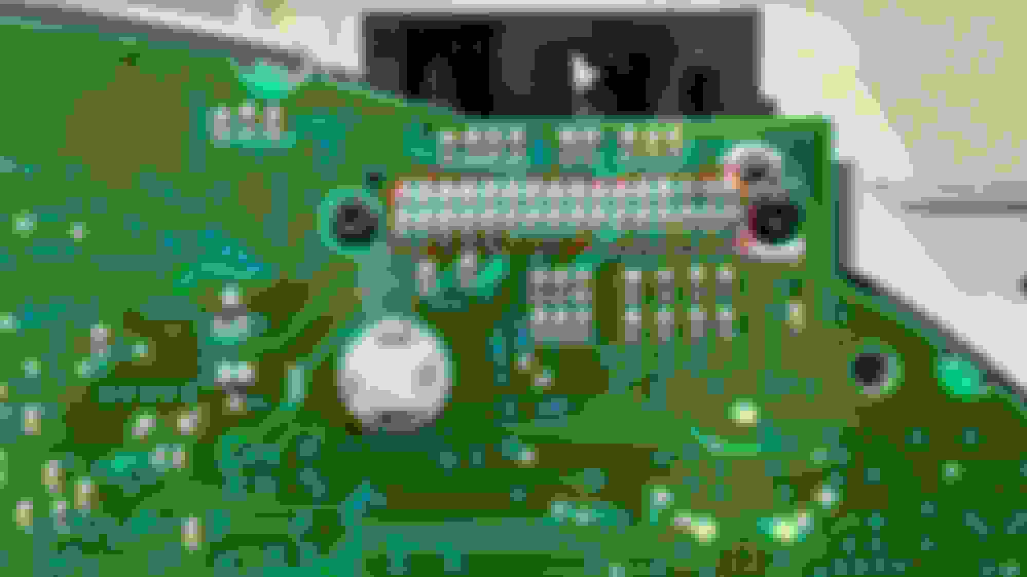
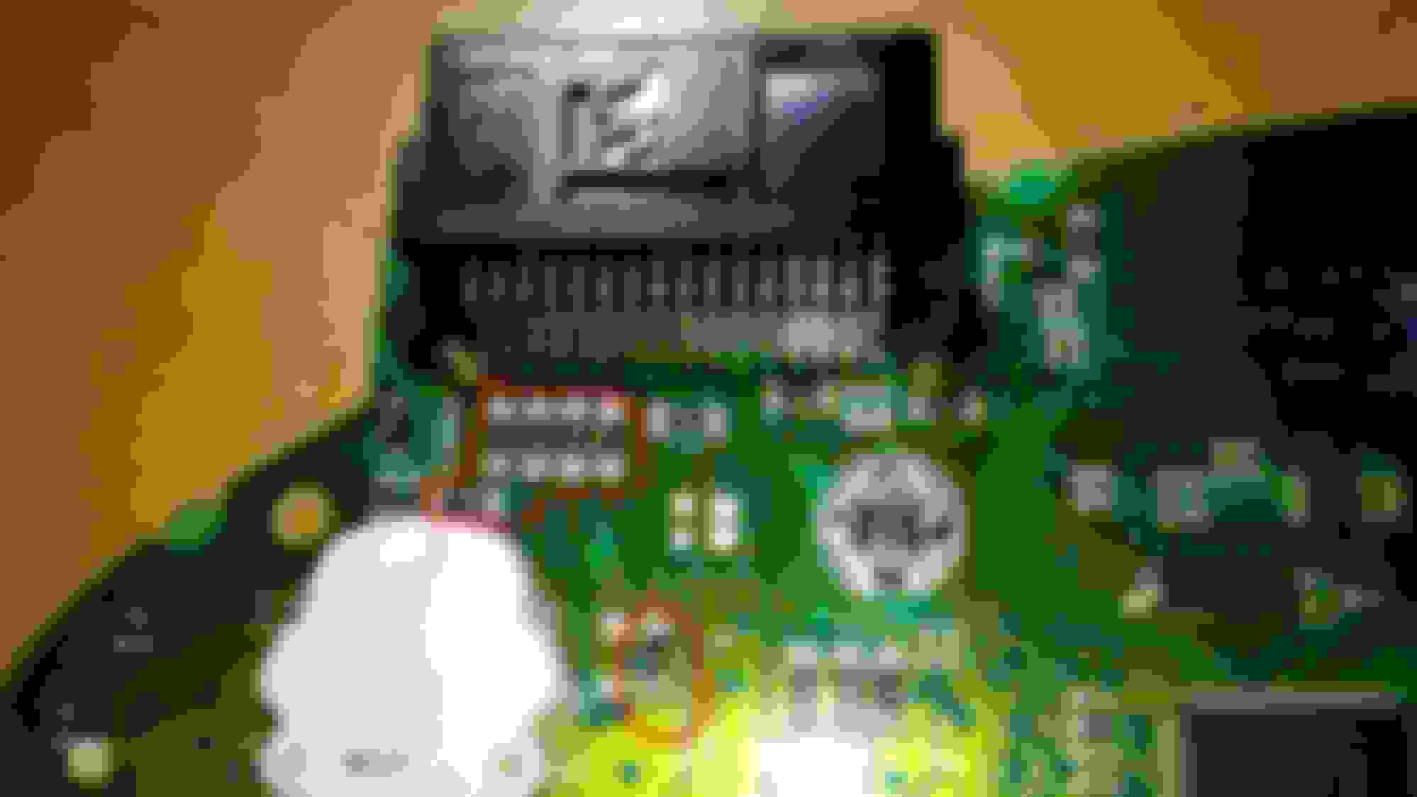
Dvo1, You're the man!!! I re-soldered all 32 pins to the board and then re-soldered everything in the Red Area and my light went out!!!! When I say re-solder, all I really did was hit each solder with a hot iron to re-melt it. Worked like a charm.
Some other tips for others: Twist each gauge needle CCW until it stops and then put a pencil mark where the tip is before prying them off. It makes re-assembly much easier. I also broke a few of the heat stakes that held the needle assembly together. A little super glue fixed this.
Not sure if this was related, but the fuse to my ODB-II blew and my drive cycle got reset. No big deal, but when I went to get inspected (Mass resident) I got rejected and have to go back after a drive cycle is complete (that was after I replaced the fuse).
How did you get the needles off? I have this same problem and have done all the steps you recommended so far, but I can't seem to get the needles off in order to solder on the other side of the board.
How did you get the needles off? I have this same problem and have done all the steps you recommended so far, but I can't seem to get the needles off in order to solder on the other side of the board.
Thanks.
Todd,
I struggled here as well. Believe it or not, they are just slid onto the gauge shafts. I used a pair of scissors to act as a pry bar on both sides of the needle. The needle assembly will fall apart into three pieces and I used a little super glue to hold the pieces back together. I know it sounds ridiculous and sketchy but it worked.
I can't emphasize enough to mark with a pencil on the gauge panel the max rotation points of the needles before prying them off.
**Update**
When you go to glue the needle assembly back together, you may need to clean out the inside edge of the outer cap. It looks like the original manufacturer held these three pieces together by what's called heat staking/swaging process. It leaves a bur edge on the inside of the outer cap that gets in the way when trying to reassemble. I found an exacto knife cleaned this up fine.
I re-soldered all of the components but ignored the IC, transistors (3 legged) and the really small components.
So, did you re-solder all the surface mount capacitors or were those among the "small components" you skipped?
There are quite a few of the capacitors so it seems the cold joint would most likely have been with one of those since re-soldering the connector pins didn't work for you. I don't like soldering because my hands aren't all that steady, so I don't want to try soldering anything I don't have to. So far I have re-soldering the connector pins twice and still have the problem.
See the video of how mine is behaving (this is after re-soldering the connector pins twice).
Todd, I watched your video and mine was doing the same. I only re-soldered the two legged components. Maybe one three legged, but the IC's/Chips with 6 legs or more I left alone. I used a needle point soldering iron set to probably 700-750F. Start with the bigger components and after a few you get used to it and the smaller ones don't seem so small.
Thanks to the information provided by Chris_C, I was able to get this fixed.
Borrowing a strong magnifier, I identified what I thought were the components most likely to be the cause. I re-soldered those and that did not work.
Next, I identified the second most likely and re-soldered. That didn't work.
Then I tried a third group, re-soldered, and that fixed it. So, I don't know if there were multiple connections that needed fixing and it took three tries to get them all, or if it/all was in the third group.
Attached is a picture with the third group of components that I soldered circled in red (note, these are on the back side of the board that you can only get to by removing the needles).
Nice work Todd. Glad to hear it worked out for you.
I got mine to stay off and not covered.
Pulled instrument cover and connector on left- wiggled and it flickered.
Found if I held pressure it would stay off. Cut chunk of cardboard and wedged in between connector and cluster.
Stays off but comes on during starting as it should then goes back out.
Really easy to get cover off.
YouTube has good videos for this but I just looked at where covers were and started in. 30 minutes and I was done.
Have similar problem with my 05 f150, brake light stays on, parking brake switch is fine but when I disconnect brake fluid sensor switch light goes out, plugged in light stays on
 06-16-2015, 03:52 PM